Report_example (*)
advertisement
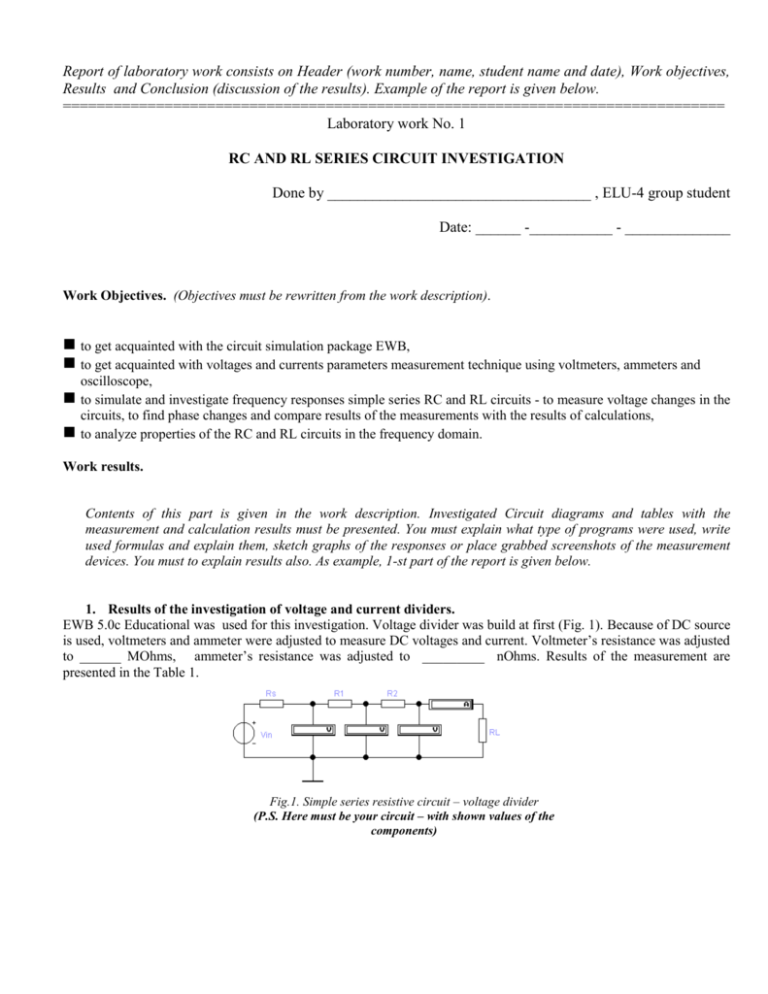
Report of laboratory work consists on Header (work number, name, student name and date), Work objectives, Results and Conclusion (discussion of the results). Example of the report is given below. ============================================================================== Laboratory work No. 1 RC AND RL SERIES CIRCUIT INVESTIGATION Done by ___________________________________ , ELU-4 group student Date: ______ -___________ - ______________ Work Objectives. (Objectives must be rewritten from the work description). to get acquainted with the circuit simulation package EWB, to get acquainted with voltages and currents parameters measurement technique using voltmeters, ammeters and oscilloscope, to simulate and investigate frequency responses simple series RC and RL circuits - to measure voltage changes in the circuits, to find phase changes and compare results of the measurements with the results of calculations, to analyze properties of the RC and RL circuits in the frequency domain. Work results. Contents of this part is given in the work description. Investigated Circuit diagrams and tables with the measurement and calculation results must be presented. You must explain what type of programs were used, write used formulas and explain them, sketch graphs of the responses or place grabbed screenshots of the measurement devices. You must to explain results also. As example, 1-st part of the report is given below. 1. Results of the investigation of voltage and current dividers. EWB 5.0c Educational was used for this investigation. Voltage divider was build at first (Fig. 1). Because of DC source is used, voltmeters and ammeter were adjusted to measure DC voltages and current. Voltmeter’s resistance was adjusted to ______ MOhms, ammeter’s resistance was adjusted to _________ nOhms. Results of the measurement are presented in the Table 1. Fig.1. Simple series resistive circuit – voltage divider (P.S. Here must be your circuit – with shown values of the components) Table 1. Series resistive circuit investigation results Results Measurement Calculation Vin, V IL, mA 2.5 2.5 10 V1, V V2, V 7.5 7.5 V3, V 5 5 2.5 2.5 Voltages and current in the circuit were calculated also. MathCAD version 8.0 was used. Load current was calculated at first and node voltages later. List of used MathCAD expressions is given below. Vin 10 1 10 3 Rs 1 10 3 R1 Vin IL ( Rs R1 IL ( R1 V1 V2 V3 IL ( R2 IL 2.5 10 R2 R2 R2 1 10 3 RL 1 10 3 3 RL) RL) RL) V1 7.5 V2 5 IL RL V3 2.5 P.S. All done calculations could be presented in another form. Different formulas could be used also. As example – Voltage V1 could be calculated as follows: V1 Vin R1 R2 RS RL R1 R2 RS . Results of calculation are presented in the table 1. From the analysis of the data in the table 1 follows, that results of calculation are the same as received using EWB voltmeters and ammeters. It proves, that series connected resistors are acting as voltage divider. Results obtained by EWB package corresponds theory. …………………………………… …………………………………… ………………………………. …………………………………………… ……………………………………… ………………………………………. Conclusions. Discussion of the obtained results, comparison of measured and calculated results, explanation of the investigated circuits action must be presented. P.S. Short answers to the control questions are preferable, because of work report will be allowed to use in defence of work.


