Lab 5.6.1: Basic RIP Configuration (Instructor Version)
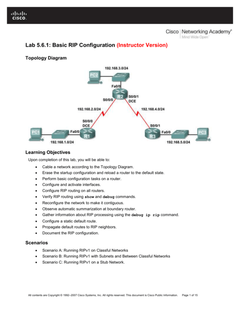
Topology Diagram
Learning Objectives
Upon completion of this lab, you will be able to:
Cable a network according to the Topology Diagram.
Erase the startup configuration and reload a router to the default state.
Perform basic configuration tasks on a router.
Configure and activate interfaces.
Configure RIP routing on all routers.
Verify RIP routing using show and debug commands.
Reconfigure the network to make it contiguous.
Observe automatic summarization at boundary router.
Gather information about RIP processing using the debug ip rip command.
Configure a static default route.
Propagate default routes to RIP neighbors.
Document the RIP configuration.
Scenarios
Scenario A: Running RIPv1 on Classful Networks
Scenario B: Running RIPv1 with Subnets and Between Classful Networks
Scenario C: Running RIPv1 on a Stub Network.
All contents are Copyright © 1992–2007 Cisco Systems, Inc. All rights reserved. This document is Cisco Public Information.
Page 1 of 15
CCNA Exploration
Routing Protocols and Concepts: RIP version 1
Lab 5.6.1: Basic RIP Configuration
Scenario A: Running RIPv1 on Classful Networks
Topology Diagram
Addressing Table
Device
Interface
IP Address
Subnet Mask
Default Gateway
Fa0/0
192.168.1.1
255.255.255.0
N/A
S0/0/0
192.168.2.1
255.255.255.0
N/A
Fa0/0
192.168.3.1
255.255.255.0
N/A
S0/0/0
192.168.2.2
255.255.255.0
N/A
S0/0/1
192.168.4.2
255.255.255.0
N/A
Fa0/0
192.168.5.1
255.255.255.0
N/A
S0/0/1
192.168.4.1
255.255.255.0
N/A
PC1
NIC
192.168.1.10
255.255.255.0
192.168.1.1
PC2
NIC
192.168.3.10
255.255.255.0
192.168.3.1
PC3
NIC
192.168.5.10
255.255.255.0
192.168.5.1
R1
R2
R3
Task 1: Prepare the Network.
Step 1: Cable a network that is similar to the one in the Topology Diagram.
You can use any current router in your lab as long as it has the required interfaces shown in the topology.
Note: If you use 1700, 2500, or 2600 routers, the router outputs and interface descriptions will appear
different.
Step 2: Clear any existing configurations on the routers.
All contents are Copyright © 1992–2007 Cisco Systems, Inc. All rights reserved. This document is Cisco Public Information.
Page 2 of 15
CCNA Exploration
Routing Protocols and Concepts: RIP version 1
Lab 5.6.1: Basic RIP Configuration
Task 2: Perform Basic Router Configurations.
Perform basic configuration of the R1, R2, and R3 routers according to the following guidelines:
1. Configure the router hostname.
2. Disable DNS lookup.
3. Configure an EXEC mode password.
4. Configure a message-of-the-day banner.
5. Configure a password for console connections.
6. Configure a password for VTY connections.
Task 3: Configure and Activate Serial and Ethernet Addresses.
Step 1: Configure interfaces on R1, R2, and R3.
Configure the interfaces on the R1, R2, and R3 routers with the IP addresses from the table under the
Topology Diagram.
Step 2: Verify IP addressing and interfaces.
Use the show ip interface brief command to verify that the IP addressing is correct and that the
interfaces are active.
When you have finished, be sure to save the running configuration to the NVRAM of the router.
Step 3: Configure Ethernet interfaces of PC1, PC2, and PC3.
Configure the Ethernet interfaces of PC1, PC2, and PC3 with the IP addresses and default gateways
from the table under the Topology Diagram.
Step 4: Test the PC configuration by pinging the default gateway from the PC.
Task 4: Configure RIP.
Step 1: Enable dynamic routing.
To enable a dynamic routing protocol, enter global configuration mode and use the router command.
Enter router ? at the global configuration prompt to a see a list of available routing protocols on your
router.
To enable RIP, enter the command router rip in global configuration mode.
R1(config)#router rip
R1(config-router)#
Step 2: Enter classful network addresses.
Once you are in routing configuration mode, enter the classful network address for each directly
connected network, using the network command.
R1(config-router)#network 192.168.1.0
R1(config-router)#network 192.168.2.0
R1(config-router)#
All contents are Copyright © 1992–2007 Cisco Systems, Inc. All rights reserved. This document is Cisco Public Information.
Page 3 of 15
CCNA Exploration
Routing Protocols and Concepts: RIP version 1
Lab 5.6.1: Basic RIP Configuration
The network command:
Enables RIP on all interfaces that belong to this network. These interfaces will now both send and
receive RIP updates.
Advertises this network in RIP routing updates sent to other routers every 30 seconds.
When you are finished with the RIP configuration, return to privileged EXEC mode and save the current
configuration to NVRAM.
R1(config-router)#end
%SYS-5-CONFIG_I: Configured from console by console
R1#copy run start
Step 3: Configure RIP on the R2 router using the router rip and network commands.
R2(config)#router rip
R2(config-router)#network 192.168.2.0
R2(config-router)#network 192.168.3.0
R2(config-router)#network 192.168.4.0
R2(config-router)#end
%SYS-5-CONFIG_I: Configured from console by console
R2#copy run start
When you are finished with the RIP configuration, return to privileged EXEC mode and save the current
configuration to NVRAM.
Step 4: Configure RIP on the R3 router using the router rip and network commands.
R3(config)#router rip
R3(config-router)#network 192.168.4.0
R3(config-router)#network 192.168.5.0
R3(config-router)#end
%SYS-5-CONFIG_I: Configured from console by console
R3# copy run start
When you are finished with the RIP configuration, return to privileged EXEC mode and save the current
configuration to NVRAM.
Task 5: Verify RIP Routing.
Step 1: Use the show ip route command to verify that each router has all of the networks in the
topology entered in the routing table.
Routes learned through RIP are coded with an R in the routing table. If the tables are not converged as
shown here, troubleshoot your configuration. Did you verify that the configured interfaces are active? Did
you configure RIP correctly? Return to Task 3 and Task 4 to review the steps necessary to achieve
convergence.
All contents are Copyright © 1992–2007 Cisco Systems, Inc. All rights reserved. This document is Cisco Public Information.
Page 4 of 15
CCNA Exploration
Routing Protocols and Concepts: RIP version 1
Lab 5.6.1: Basic RIP Configuration
R1#show ip route
Codes: C - connected, S - static, I - IGRP, R - RIP, M - mobile, B - BGP
D - EIGRP, EX - EIGRP external, O - OSPF, IA - OSPF inter area
N1 - OSPF NSSA external type 1, N2 - OSPF NSSA external type 2
E1 - OSPF external type 1, E2 - OSPF external type 2, E - EGP
i - IS-IS, L1 - IS-IS level-1, L2 - IS-IS level-2, ia - IS-IS inter area
* - candidate default, U - per-user static route, o - ODR
P - periodic downloaded static route
Gateway of last resort is not set
C
C
R
R
R
R1#
192.168.1.0/24
192.168.2.0/24
192.168.3.0/24
192.168.4.0/24
192.168.5.0/24
is directly
is directly
[120/1] via
[120/1] via
[120/2] via
connected, FastEthernet0/0
connected, Serial0/0/0
192.168.2.2, 00:00:04, Serial0/0/0
192.168.2.2, 00:00:04, Serial0/0/0
192.168.2.2, 00:00:04, Serial0/0/0
[120/1] via
is directly
is directly
is directly
[120/1] via
192.168.2.1, 00:00:22, Serial0/0/0
connected, Serial0/0/0
connected, FastEthernet0/0
connected, Serial0/0/1
192.168.4.1, 00:00:23, Serial0/0/1
[120/2] via
[120/1] via
[120/1] via
is directly
is directly
192.168.4.2, 00:00:18, Serial0/0/1
192.168.4.2, 00:00:18, Serial0/0/1
192.168.4.2, 00:00:18, Serial0/0/1
connected, Serial0/0/1
connected, FastEthernet0/0
R2#show ip route
<Output omitted>
R
C
C
C
R
R2#
192.168.1.0/24
192.168.2.0/24
192.168.3.0/24
192.168.4.0/24
192.168.5.0/24
R3#show ip route
<Output omitted>
R
R
R
C
C
R3#
192.168.1.0/24
192.168.2.0/24
192.168.3.0/24
192.168.4.0/24
192.168.5.0/24
Step 2: Use the show ip protocols command to view information about the routing processes.
The show ip protocols command can be used to view information about the routing processes that
are occurring on the router. This output can be used to verify most RIP parameters to confirm that:
RIP routing is configured
The correct interfaces send and receive RIP updates
The router advertises the correct networks
RIP neighbors are sending updates
All contents are Copyright © 1992–2007 Cisco Systems, Inc. All rights reserved. This document is Cisco Public Information.
Page 5 of 15
CCNA Exploration
Routing Protocols and Concepts: RIP version 1
Lab 5.6.1: Basic RIP Configuration
R1#show ip protocols
Routing Protocol is "rip"
Sending updates every 30 seconds, next due in 16 seconds
Invalid after 180 seconds, hold down 180, flushed after 240
Outgoing update filter list for all interfaces is not set
Incoming update filter list for all interfaces is not set
Redistributing: rip
Default version control: send version 1, receive any version
Interface
Send Recv Triggered RIP Key-chain
FastEthernet0/0
1
2 1
Serial0/0/0
1
2 1
Automatic network summarization is in effect
Maximum path: 4
Routing for Networks:
192.168.1.0
192.168.2.0
Passive Interface(s):
Routing Information Sources:
Gateway
Distance
Last Update
192.168.2.2
120
Distance: (default is 120)
R1#
R1 is indeed configured with RIP. R1 is sending and receiving RIP updates on FastEthernet0/0 and
Serial0/0/0. R1 is advertising networks 192.168.1.0 and 192.168.2.0. R1 has one routing information
source. R2 is sending R1 updates.
Step 3: Use the debug ip rip command to view the RIP messages being sent and received.
Rip updates are sent every 30 seconds so you may have to wait for debug information to be displayed.
R1#debug ip rip
R1#RIP: received v1 update from 192.168.2.2 on Serial0/0/0
192.168.3.0 in 1 hops
192.168.4.0 in 1 hops
192.168.5.0 in 2 hops
RIP: sending v1 update to 255.255.255.255 via FastEthernet0/0 (192.168.1.1)
RIP: build update entries
network 192.168.2.0 metric 1
network 192.168.3.0 metric 2
network 192.168.4.0 metric 2
network 192.168.5.0 metric 3
RIP: sending v1 update to 255.255.255.255 via Serial0/0/0 (192.168.2.1)
RIP: build update entries
network 192.168.1.0 metric 1
The debug output shows that R1 receives an update from R2. Notice how this update includes all the
networks that R1 does not already have in its routing table. Because the FastEthernet0/0 interface
belongs to the 192.168.1.0 network configured under RIP, R1 builds an update to send out that interface.
The update includes all networks known to R1 except the network of the interface. Finally, R1 builds an
update to send to R2. Because of split horizon, R1 only includes the 192.168.1.0 network in the update.
Step 4: Discontinue the debug output with the undebug all command.
R1#undebug all
All possible debugging has been turned off
All contents are Copyright © 1992–2007 Cisco Systems, Inc. All rights reserved. This document is Cisco Public Information.
Page 6 of 15
CCNA Exploration
Routing Protocols and Concepts: RIP version 1
Lab 5.6.1: Basic RIP Configuration
Scenario B: Running RIPv1 with Subnets and Between Classful Networks
Topology Diagram
Addressing Table
Device
Interface
IP Address
Subnet Mask
Default Gateway
Fa0/0
172.30.1.1
255.255.255.0
N/A
S0/0/0
172.30.2.1
255.255.255.0
N/A
Fa0/0
172.30.3.1
255.255.255.0
N/A
S0/0/0
172.30.2.2
255.255.255.0
N/A
S0/0/1
192.168.4.9
255.255.255.252
N/A
Fa0/0
192.168.5.1
255.255.255.0
N/A
S0/0/1
192.168.4.10
255.255.255.252
N/A
PC1
NIC
172.30.1.10
255.255.255.0
172.30.1.1
PC2
NIC
172.30.3.10
255.255.255.0
172.30.3.1
PC3
NIC
192.168.5.10
255.255.255.0
192.168.5.1
R1
R2
R3
Task 1: Make Changes between Scenario A and Scenario B
Step 1: Change the IP addressing on the interfaces as shown in the Topology Diagram and the
Addressing Table.
Sometimes when changing the IP address on a serial interface, you may need to reset that interface by
using the shutdown command, waiting for the LINK-5-CHANGED message, and then using the no
shutdown command. This process will force the IOS to starting using the new IP address.
All contents are Copyright © 1992–2007 Cisco Systems, Inc. All rights reserved. This document is Cisco Public Information.
Page 7 of 15
CCNA Exploration
Routing Protocols and Concepts: RIP version 1
Lab 5.6.1: Basic RIP Configuration
R1(config)#int s0/0/0
R1(config-if)#ip add 172.30.2.1 255.255.255.0
R1(config-if)#shutdown
%LINK-5-CHANGED: Interface Serial0/0/0, changed state to administratively
down
%LINEPROTO-5-UPDOWN: Line protocol on Interface Serial0/0/0, changed state to
down
R1(config-if)#no shutdown
%LINK-5-CHANGED: Interface Serial0/0/0, changed state to up
R1(config-if)#
%LINEPROTO-5-UPDOWN: Line protocol on Interface Serial0/0/0, changed state to
up
Step 2: Verify that routers are active.
After reconfiguring all the interfaces on all three routers, verify that all necessary interfaces are active with
the show ip interface brief command.
Step 3: Remove the RIP configurations from each router.
Although you can remove the old network commands with the no version of the command, it is more
efficient to simply remove RIP and start over. Remove the RIP configurations from each router with the
no router rip global configuration command. This will remove all the RIP configuration commands
including the network commands.
R1(config)#no router rip
R2(config)#no router rip
R3(config)#no router rip
Task 2: Configure RIP
Step 1: Configure RIP routing on R1 as shown below.
R1(config)#router rip
R1(config-router)#network 172.30.0.0
Notice that only a single network statement is needed for R1. This statement includes both interfaces on
different subnets of the 172.30.0.0 major network.
Step 2: Configure R1 to stop sending updates out the FastEthernet0/0 interface.
Sending updates out this interface wastes the bandwidth and processing resources of all devices on the
LAN. In addition, advertising updates on a broadcast network is a security risk. RIP updates can be
intercepted with packet sniffing software. Routing updates can be modified and sent back to the router,
corrupting the router table with false metrics that misdirects traffic.
The passive-interface fastethernet 0/0 command is used to disable sending RIPv1 updates
out that interface. When you are finished with the RIP configuration, return to privileged EXEC mode and
save the current configuration to NVRAM.
R1(config-router)#passive-interface fastethernet 0/0
R1(config-router)#end
%SYS-5-CONFIG_I: Configured from console by console
R1#copy run start
All contents are Copyright © 1992–2007 Cisco Systems, Inc. All rights reserved. This document is Cisco Public Information.
Page 8 of 15
CCNA Exploration
Routing Protocols and Concepts: RIP version 1
Lab 5.6.1: Basic RIP Configuration
Step 2: Configure RIP routing on R2 as shown below.
R2(config)#router rip
R2(config-router)#network 172.30.0.0
R2(config-router)#network 192.168.4.0
R2(config-router)#passive-interface fastethernet 0/0
R2(config-router)#end
%SYS-5-CONFIG_I: Configured from console by console
R2#copy run start
Again notice that only a single network statement is needed for the two subnets of 172.30.0.0. This
statement includes both interfaces, on different subnets, of the 172.30.0.0 major network. The network for
the WAN link between R2 and R3 is also configured.
When you are finished with the RIP configuration, return to privileged EXEC mode and save the current
configuration to NVRAM.
Step 3: Configure RIP routing on R3 as shown below.
R3(config)#router rip
R3(config-router)#network 192.168.4.0
R3(config-router)#network 192.168.5.0
R3(config-router)#passive-interface fastethernet 0/0
R3(config-router)#end
%SYS-5-CONFIG_I: Configured from console by console
R3#copy run start
When you are finished with the RIP configuration, return to privileged EXEC mode and save the current
configuration to NVRAM.
Task 3: Verify RIP Routing
Step 1: Use the show ip route command to verify that each router has all of the networks in the
topology in the routing table.
R1#show ip route
<Output omitted>
C
C
R
R
R
R1#
172.30.0.0/24 is subnetted, 3 subnets
172.30.1.0 is directly connected, FastEthernet0/0
172.30.2.0 is directly connected, Serial0/0/0
172.30.3.0 [120/1] via 172.30.2.2, 00:00:22, Serial0/0/0
192.168.4.0/24 [120/1] via 172.30.2.2, 00:00:22, Serial0/0/0
192.168.5.0/24 [120/2] via 172.30.2.2, 00:00:22, Serial0/0/0
Note: RIPv1 is a classful routing protocol. Classful routing protocols do not send the subnet mask with
network in routing updates. For example, 172.30.1.0 is sent by R2 to R1 without any subnet mask
information.
All contents are Copyright © 1992–2007 Cisco Systems, Inc. All rights reserved. This document is Cisco Public Information.
Page 9 of 15
CCNA Exploration
Routing Protocols and Concepts: RIP version 1
Lab 5.6.1: Basic RIP Configuration
R2#show ip route
<Output omitted>
R
C
C
C
R
R2#
172.30.0.0/24 is subnetted, 3 subnets
172.30.1.0 [120/1] via 172.30.2.1, 00:00:04, Serial0/0/0
172.30.2.0 is directly connected, Serial0/0/0
172.30.3.0 is directly connected, FastEthernet0/0
192.168.4.0/30 is subnetted, 1 subnets
192.168.4.8 is directly connected, Serial0/0/1
192.168.5.0/24 [120/1] via 192.168.4.10, 00:00:19, Serial0/0/1
R3#show ip route
<Output omitted>
R
C
C
172.30.0.0/16 [120/1] via 192.168.4.9, 00:00:22, Serial0/0/1
192.168.4.0/30 is subnetted, 1 subnets
192.168.4.8 is directly connected, Serial0/0/1
192.168.5.0/24 is directly connected, FastEthernet0/0
Step 2: Verify that all necessary interfaces are active.
If one or more routing tables does not have a converged routing table, first make sure that all necessary
interfaces are active with show ip interface brief.
Then use show ip protocols to verify the RIP configuration. Notice in the output from this command
that the FastEthernet0/0 interface is no longer listed under Interface but is now listed under a new
section of the output: Passive Interface(s).
R1#show ip protocols
Routing Protocol is "rip"
Sending updates every 30 seconds, next due in 20 seconds
Invalid after 180 seconds, hold down 180, flushed after 240
Outgoing update filter list for all interfaces is not set
Incoming update filter list for all interfaces is not set
Redistributing: rip
Default version control: send version 2, receive version 2
Interface
Send Recv Triggered RIP Key-chain
Serial0/1/0
2
2
Automatic network summarization is in effect
Maximum path: 4
Routing for Networks:
172.30.0.0
209.165.200.0
Passive Interface(s):
FastEthernet0/0
Routing Information Sources:
Gateway
Distance
Last Update
209.165.200.229
120
00:00:15
Distance: (default is 120)
All contents are Copyright © 1992–2007 Cisco Systems, Inc. All rights reserved. This document is Cisco Public Information.
Page 10 of 15
CCNA Exploration
Routing Protocols and Concepts: RIP version 1
Lab 5.6.1: Basic RIP Configuration
Step 3: View the RIP messages being sent and received.
To view the RIP messages being sent and received use the debug ip rip command. Notice that RIP
updates are not sent out of the fa0/0 interface because of the passive-interface fastethernet
0/0 command.
R1#debug ip rip
R1#RIP: sending v1 update to 255.255.255.255 via Serial0/0/0 (172.30.2.1)
RIP: build update entries
network 172.30.1.0 metric 1
RIP: received v1 update from 172.30.2.2 on Serial0/0/0
172.30.3.0 in 1 hops
Step 4: Discontinue the debug output with the undebug all command.
R1#undebug all
All possible debugging has been turned off
All contents are Copyright © 1992–2007 Cisco Systems, Inc. All rights reserved. This document is Cisco Public Information.
Page 11 of 15
CCNA Exploration
Routing Protocols and Concepts: RIP version 1
Lab 5.6.1: Basic RIP Configuration
Scenario C: Running RIPv1 on a Stub Network
Topology Diagram
Background
In this scenario we will modify Scenario B to only run RIP between R1 and R2. Scenario C is a typical
configuration for most companies connecting a stub network to a central headquarters router or an ISP.
Typically, a company runs a dynamic routing protocol (RIPv1 in our case) within the local network but
finds it unnecessary to run a dynamic routing protocol between the company’s gateway router and the
ISP. For example, colleges with multiple campuses often run a dynamic routing protocol between
campuses but use default routing to the ISP for access to the Internet. In some cases, remote campuses
may even use default routing to the main campus, choosing to use dynamic routing only locally.
To keep our example simple, for Scenario C, we left the addressing intact from Scenario B. Let’s assume
that R3 is the ISP for our Company XYZ, which consists of the R1 and R2 routers using the 172.30.0.0/16
major network, subnetted with a /24 mask. Company XYZ is a stub network, meaning that there is only
one way in and one way out of the 172.30.0.0/16 network—in via R2 (the gateway router) and out via R3
(the ISP). It doesn’t make sense for R2 to send R3 RIP updates for the 172.30.0.0 network every 30
seconds, because R3 has no other way to get to 172.30.0.0 except through R2. It makes more sense for
R3 to have a static route configured for the 172.30.0.0/16 network pointing to R2.
How about traffic from Company XYZ toward the Internet? It makes no sense for R3 to send over
120,000 summarized Internet routes to R2. All R2 needs to know is that if a packet is not destined for a
host on the 172.30.0.0 network, then it should send the packet to the ISP, R3. This is the same for all
other Company XYZ routers (only R1 in our case). They should send all traffic not destined for the
172.30.0.0 network to R2. R2 would then forward the traffic to R3.
Task 1: Make Changes between Scenario B and Scenario C.
Step 1: Remove network 192.168.4.0 from the RIP configuration for R2.
Remove network 192.168.4.0 from the RIP configuration for R2, because no updates will be sent
between R2 and R3 and we don’t want to advertise the 192.168.4.0 network to R1.
R2(config)#router rip
R2(config-router)#no network 192.168.4.0
All contents are Copyright © 1992–2007 Cisco Systems, Inc. All rights reserved. This document is Cisco Public Information.
Page 12 of 15
CCNA Exploration
Routing Protocols and Concepts: RIP version 1
Lab 5.6.1: Basic RIP Configuration
Step 2: Completely remove RIP routing from R3.
R3(config)#no router rip
Task 2: Configure the Static Route on R3 for the 172.30.0.0/16 network.
Because R3 and R2 are not exchanging RIP updates, we need to configure a static route on R3 for the
172.30.0.0/16 network. This will send all 172.30.0.0/16 traffic to R2.
R3(config)#ip route 172.30.0.0 255.255.252.0 serial0/0/1
Task 3: Configure a Default Static Route on R2.
Step 1: Configure R2 to send default traffic to R3.
Configure a default static route on R2 that will send all default traffic—packets with destination IP
addresses that do not match a specific route in the routing table—to R3.
R2(config)# ip route 0.0.0.0 0.0.0.0 serial 0/0/1
Step 2: Configure R2 to send default static route information to R1.
The default-information originate command is used to configure R2 to include the default static
route with its RIP updates. Configure this command on R2 so that the default static route information is
sent to R1.
R2(config)#router rip
R2(config-router)#default-information originate
R2(config-router)#
Note: Sometimes it is necessary to clear the RIP routing process before the default-information
originate command will work. First, try the command clear ip route * on both R1 and R2. This
command will cause the routers to immediately flush routes in the routing table and request updates from
each other. Sometimes this does not work with RIP. If the default route information is still not sent to R1,
save the configuration on R1 and R2 and then reload both routers. Doing this will reset the hardware and
both routers will restart the RIP routing process.
Task 4: Verify RIP Routing.
Step 1: Use the show ip route command to view the routing table on R2 and R1.
R2#show ip route
Codes: C - connected, S - static, I - IGRP, R - RIP, M - mobile, B - BGP
D - EIGRP, EX - EIGRP external, O - OSPF, IA - OSPF inter area
N1 - OSPF NSSA external type 1, N2 - OSPF NSSA external type 2
E1 - OSPF external type 1, E2 - OSPF external type 2, E - EGP
i - IS-IS, L1 - IS-IS level-1, L2 - IS-IS level-2, ia - IS-IS inter area
* - candidate default, U - per-user static route, o - ODR
P - periodic downloaded static route
Gateway of last resort is 0.0.0.0 to network 0.0.0.0
C
C
R
172.30.0.0/24
172.30.2.0
172.30.3.0
172.30.1.0
is subnetted, 3 subnets
is directly connected, Serial0/0/0
is directly connected, FastEthernet0/0
[120/1] via 172.30.2.1, 00:00:16, Serial0/0/0
All contents are Copyright © 1992–2007 Cisco Systems, Inc. All rights reserved. This document is Cisco Public Information.
Page 13 of 15
CCNA Exploration
Routing Protocols and Concepts: RIP version 1
C
S*
Lab 5.6.1: Basic RIP Configuration
192.168.4.0/30 is subnetted, 1 subnets
192.168.4.8 is directly connected, Serial0/0/1
0.0.0.0/0 is directly connected, Serial0/0/1
Notice that R2 now has a static route tagged as a candidate default.
R1#show ip route
Codes: C - connected, S - static, I - IGRP, R - RIP, M - mobile, B - BGP
D - EIGRP, EX - EIGRP external, O - OSPF, IA - OSPF inter area
N1 - OSPF NSSA external type 1, N2 - OSPF NSSA external type 2
E1 - OSPF external type 1, E2 - OSPF external type 2, E - EGP
i - IS-IS, L1 - IS-IS level-1, L2 - IS-IS level-2, ia - IS-IS inter area
* - candidate default, U - per-user static route, o - ODR
P - periodic downloaded static route
Gateway of last resort is 172.30.2.2 to network 0.0.0.0
C
R
C
R*
172.30.0.0/24 is subnetted, 3 subnets
172.30.2.0 is directly connected, Serial0/0/0
172.30.3.0 [120/1] via 172.30.2.2, 00:00:05, Serial0/0/0
172.30.1.0 is directly connected, FastEthernet0/0
0.0.0.0/0 [120/1] via 172.30.2.2, 00:00:19, Serial0/0/0
Notice that R1 now has a RIP route tagged as a candidate default route. The route is the “quad-zero”
default route sent by R2. R1 will now send default traffic to the Gateway of last resort at 172.30.2.2,
which is the IP address of R2.
Step 2: View the RIP updates that are sent and received on R1 with the debug ip rip command.
R1#debug ip rip
RIP protocol debugging is on
R1#RIP: sending v1 update to 255.255.255.255 via Serial0/0/0 (172.30.2.1)
RIP: build update entries
network 172.30.1.0 metric 1
RIP: received v1 update from 172.30.2.2 on Serial0/0/0
0.0.0.0 in 1 hops
172.30.3.0 in 1 hops
Notice that R1 is receiving the default route from R2.
Step 3: Discontinue the debug output with the undebug all command.
R1#undebug all
All possible debugging has been turned off
Step 4: Use the show ip route command to view the routing table on R3.
R3#show ip route
<Output omitted>
S
C
C
172.30.0.0/16 is directly connected, Serial0/0/1
192.168.4.0/30 is subnetted, 1 subnets
192.168.4.8 is directly connected, Serial0/0/1
192.168.5.0/24 is directly connected, FastEthernet0/0
Notice that RIP is not being used on R3. The only route that is not directly connected is the static route.
All contents are Copyright © 1992–2007 Cisco Systems, Inc. All rights reserved. This document is Cisco Public Information.
Page 14 of 15
CCNA Exploration
Routing Protocols and Concepts: RIP version 1
Lab 5.6.1: Basic RIP Configuration
Task 5: Document the Router Configurations
On each router, capture the following command output to a text file and save for future reference:
Running configuration
Routing table
Interface summarization
Output from show ip protocols
Task 6: Clean Up
Erase the configurations and reload the routers. Disconnect and store the cabling. For PC hosts that are
normally connected to other networks (such as the school LAN or to the Internet), reconnect the
appropriate cabling and restore the TCP/IP settings.
All contents are Copyright © 1992–2007 Cisco Systems, Inc. All rights reserved. This document is Cisco Public Information.
Page 15 of 15

