worksheet
advertisement
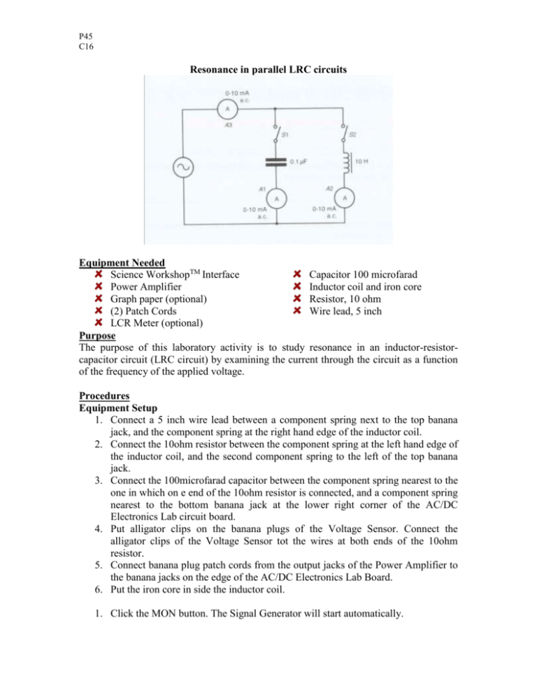
P45 C16 Resonance in parallel LRC circuits Equipment Needed Science WorkshopTM Interface Capacitor 100 microfarad Power Amplifier Inductor coil and iron core Graph paper (optional) Resistor, 10 ohm (2) Patch Cords Wire lead, 5 inch LCR Meter (optional) Purpose The purpose of this laboratory activity is to study resonance in an inductor-resistorcapacitor circuit (LRC circuit) by examining the current through the circuit as a function of the frequency of the applied voltage. Procedures Equipment Setup 1. Connect a 5 inch wire lead between a component spring next to the top banana jack, and the component spring at the right hand edge of the inductor coil. 2. Connect the 10ohm resistor between the component spring at the left hand edge of the inductor coil, and the second component spring to the left of the top banana jack. 3. Connect the 100microfarad capacitor between the component spring nearest to the one in which on e end of the 10ohm resistor is connected, and a component spring nearest to the bottom banana jack at the lower right corner of the AC/DC Electronics Lab circuit board. 4. Put alligator clips on the banana plugs of the Voltage Sensor. Connect the alligator clips of the Voltage Sensor tot the wires at both ends of the 10ohm resistor. 5. Connect banana plug patch cords from the output jacks of the Power Amplifier to the banana jacks on the edge of the AC/DC Electronics Lab Board. 6. Put the iron core in side the inductor coil. 1. Click the MON button. The Signal Generator will start automatically. P45 C16 2. In the Graph display, record the voltage that is displayed. Find 10Hz in the Data Table. Record the voltage in the Data Table. 3. Increase the frequency by 10 Hz. Repeat Step 2 for 20Hz in the Data Table. 4. Repeat the process until 150Hz is reached. 5. Look at the Data Table and determine approximately the resonant frequency (where voltage across the resistor reaches a maximum and the output voltage and resistor voltage are in phase). 6. Click the STOP button. Turn off the switch on the back of the Power Amplifier. Result and Analyzing the Data 1. Calculate the current through the resistor and record the values in the Data Table. Graph the current versus the linear frequency. 2. Using the resonant frequency found from the Scope display, calculate the resonant angular frequency and record the value in the Data Table: ωres=2πvres 3. Calculate the theoretical resonant angular frequency using the values of the inductance and capacitance: ωres=1/(LC)1/2 Results Freq (Hz) 10 20 30 40 50 60 70 80 VR I=VR/R Item Inductance Resistance Capacitance Resonant frequency (linear) Resonant angular frequency Theoretical resonant angular frequency Freq (Hz) 90 100 110 120 130 140 150 VR I=VR/R Value mH Ω Μ Hz Hz Hz P45 C16 Conclusion


