Pumps - Grundfos
advertisement
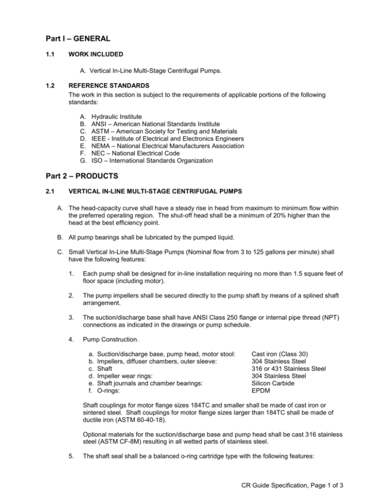
Part I – GENERAL 1.1 WORK INCLUDED A. Vertical In-Line Multi-Stage Centrifugal Pumps. 1.2 REFERENCE STANDARDS The work in this section is subject to the requirements of applicable portions of the following standards: A. B. C. D. E. F. G. Hydraulic Institute ANSI – American National Standards Institute ASTM – American Society for Testing and Materials IEEE - Institute of Electrical and Electronics Engineers NEMA – National Electrical Manufacturers Association NEC – National Electrical Code ISO – International Standards Organization Part 2 – PRODUCTS 2.1 VERTICAL IN-LINE MULTI-STAGE CENTRIFUGAL PUMPS A. The head-capacity curve shall have a steady rise in head from maximum to minimum flow within the preferred operating region. The shut-off head shall be a minimum of 20% higher than the head at the best efficiency point. B. All pump bearings shall be lubricated by the pumped liquid. C. Small Vertical In-Line Multi-Stage Pumps (Nominal flow from 3 to 125 gallons per minute) shall have the following features: 1. Each pump shall be designed for in-line installation requiring no more than 1.5 square feet of floor space (including motor). 2. The pump impellers shall be secured directly to the pump shaft by means of a splined shaft arrangement. 3. The suction/discharge base shall have ANSI Class 250 flange or internal pipe thread (NPT) connections as indicated in the drawings or pump schedule. 4. Pump Construction. a. b. c. d. e. f. Suction/discharge base, pump head, motor stool: Impellers, diffuser chambers, outer sleeve: Shaft Impeller wear rings: Shaft journals and chamber bearings: O-rings: Cast iron (Class 30) 304 Stainless Steel 316 or 431 Stainless Steel 304 Stainless Steel Silicon Carbide EPDM Shaft couplings for motor flange sizes 184TC and smaller shall be made of cast iron or sintered steel. Shaft couplings for motor flange sizes larger than 184TC shall be made of ductile iron (ASTM 60-40-18). Optional materials for the suction/discharge base and pump head shall be cast 316 stainless steel (ASTM CF-8M) resulting in all wetted parts of stainless steel. 5. The shaft seal shall be a balanced o-ring cartridge type with the following features: CR Guide Specification, Page 1 of 3 a. b. c. d. e. Collar, Drivers, Spring: Shaft Sleeve, Gland Plate: Stationary Ring: Rotating Ring: O-rings: 316 Stainless Steel 316 Stainless Steel Silicon Carbide Silicon Carbide EPDM The Silicon Carbide shall be imbedded with graphite. 6. Shaft seal replacement shall be possible without removal of any pump components other than the coupling guard, shaft coupling and motor. Pumps with motors equal to or larger than 15 hp (fifteen horsepower) shall have adequate space within the motor stool so that shaft seal replacement is possible without motor removal. 7. The maximum working temperature shall be 250 degrees F. The maximum working pressure are as follows: Connection Type 1” or 1 ¼” Internal Thread (NPT) 2” Internal Thread (NPT) ANSI Flange (Class 250) Maximum Working Pressure 232 psig 145 psig 362 psig D. Large In-line Vertical Multi-Stage Pumps (Nominal flows from 130 to 500 gallons per minute) shall have the following features: 1. Each pump shall be designed for in-line installation requiring no more than 2.5 square feet of floor space (including motor). 2. The pump impellers shall be secured directly to the smooth pump shaft by means of a split cone and nut design. 3. The suction/discharge base shall have ANSI Class 125 or Class 250 flange connections in a slip ring (rotating flange) design as indicated in the drawings or pump schedule. 4. Pump Construction. a. b. b. c. d. e. f. g. h. i. 5. Ductile Iron (ASTM 65-45-12) Ductile Iron (ASTM 65-45-12) 431 Stainless Steel Cast Iron (ASTM Class 30) 304 Stainless Steel 304 Stainless Steel Tungsten Carbide Leadless Tin Bronze Graphite Filled PTFE EPDM The shaft seal shall be a single balanced metal bellows cartridge with the following construction: a. b. c. d. e. 6. Suction/discharge base, pump head Shaft couplings, flange rings: Shaft Motor Stool Impellers, diffuser chambers, outer sleeve: Impeller wear rings: Intermediate Bearing Journals: Intermediate Chamber Bearings: Chamber Bushings: O-rings: Bellows: Shaft Sleeve, Gland Plate, Drive Collar: Stationary Ring: Rotating Ring: O-rings: 904L Stainless Steel 316 Stainless Steel Carbon Tungsten Carbide EPDM Shaft seal replacement shall be possible without removal of any pump components other than the coupling guard, motor couplings, motor and seal cover. Pumps with motors equal to or larger than 15 hp (fifteen horsepower) shall have adequate space within the motor stool so that shaft seal replacement is possible without motor removal. CR Guide Specification, Page 2 of 3 7. 2.2 The maximum working temperature shall be 250 degrees F. The maximum working pressure shall be 232 psig or 362 psig as determined by the installation requirements. MOTORS A. Motors are to be provided with the following basic features: 2.3 1. Motors shall be designed for continuous duty operation, NEMA design B with a 1.15 S.F. 2. Totally Enclosed Fan Cooled Motors are to be furnished with class “F” insulation. Open Drip Proof Motors are to be furnished with class “B” insulation. 3. Motor nameplate shall be mounted on enclosure with stainless steel fastening pins. Nameplate shall have, as a minimum, all information as described in NEMA Standard MG 120.40.1. 4. Open Drip Proof (ODP) motors shall have drip covers. 5. Motors over 50 lbs shall having lifting provisions. 6. Motors shall have a NEMA C-Flange for vertical mounting. 7. Drive end bearings shall be adequately sized so that the minimum L10 bearing life is 17,500 hours at the minimum allowable continuous flow rate for the pump. TESTING A. The pump manufacturer shall perform non-witnessed testing (in accordance with ISO9906 annex A) of pumps prior to shipment. B. The pump manufacturer shall be capable of providing certified testing of pumps prior to shipment. 2.4 WARRANTY A. The warranty period shall be a non-prorated period of 24 months from date of installation, not to exceed 30 months from date of manufacture. CR Guide Specification, Page 3 of 3

