Approach - GeekInterview.com
advertisement
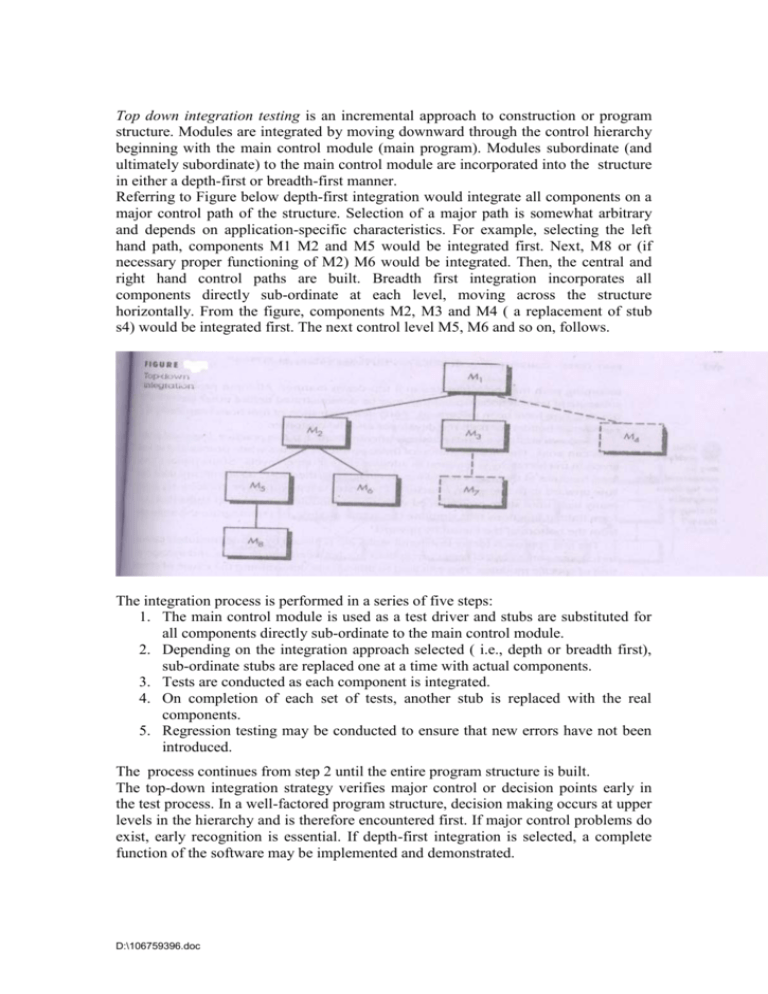
Top down integration testing is an incremental approach to construction or program structure. Modules are integrated by moving downward through the control hierarchy beginning with the main control module (main program). Modules subordinate (and ultimately subordinate) to the main control module are incorporated into the structure in either a depth-first or breadth-first manner. Referring to Figure below depth-first integration would integrate all components on a major control path of the structure. Selection of a major path is somewhat arbitrary and depends on application-specific characteristics. For example, selecting the left hand path, components M1 M2 and M5 would be integrated first. Next, M8 or (if necessary proper functioning of M2) M6 would be integrated. Then, the central and right hand control paths are built. Breadth first integration incorporates all components directly sub-ordinate at each level, moving across the structure horizontally. From the figure, components M2, M3 and M4 ( a replacement of stub s4) would be integrated first. The next control level M5, M6 and so on, follows. The integration process is performed in a series of five steps: 1. The main control module is used as a test driver and stubs are substituted for all components directly sub-ordinate to the main control module. 2. Depending on the integration approach selected ( i.e., depth or breadth first), sub-ordinate stubs are replaced one at a time with actual components. 3. Tests are conducted as each component is integrated. 4. On completion of each set of tests, another stub is replaced with the real components. 5. Regression testing may be conducted to ensure that new errors have not been introduced. The process continues from step 2 until the entire program structure is built. The top-down integration strategy verifies major control or decision points early in the test process. In a well-factored program structure, decision making occurs at upper levels in the hierarchy and is therefore encountered first. If major control problems do exist, early recognition is essential. If depth-first integration is selected, a complete function of the software may be implemented and demonstrated. D:\106759396.doc Top-down strategy sounds relatively uncomplicated, but in practice, logistical problems can arise. The most common of these problems occurs when processing at low levels in the hierarchy is required to adequately test upper levels. Stubs replace low-level modules at the beginning of top-down testing; therefore, no significant data can now upward in the program structure. The tester is left will three choices; Delay many tests until stubs are replaced with actual modules. Develop stubs that perform limited functions that simulate the actual module, or Integrate the software from the bottom of the hierarchy upward. The first approach (delay tests until stubs are replaced by actual modules) causes us to loose some control over correspondence between specific tests and incorporation of specific modules. This can lead to difficulty in determining the cause of errors and tends to violate the highly constrained nature of the top-down approach. The second approach is workable but can lead to significant overhead, as stubs become more and more complex. The third approach is called bottom-up testing. 11.4.2 Bottom-up Integration Bottom-up integration testing, as its name implies, begins construction and testing with atomic modules (i.e., components at the lowest levels in the program structure). Because components are integrated from the bottom up, processing required for components subordinate to a given level is always available and the need for stubs is eliminated. A bottom-up integration strategy may be implemented with the following steps: Low-level components are combined into clusters (sometimes called builds) that perform a specific software sub-function. A driver (a control program for testing) is written to coordinate test case input and output. The cluster is tested. Drivers are removed and clusters are combined moving upward in the program structure. Integration follows the pattern illustrated in Figure below. Components are combined to form clusters 1,2, and 3. D:\106759396.doc Each of the clusters is tested using a driver (shown as a dashed block). Components in clusters 1 and 2 are subordinate to Ma. Drivers D1 and D2 are removed and the clusters are interfaced directly to Ma. Similarly, driver D3 for cluster 3 is removed prior to integration with module Mb. Both Ma and Mb will ultimately be integrated with component Mc, and so forth. As integration moves upward the need for separate test drivers lessens. In fact, if the top two levels of program structure are integrated top down, the number of drivers can be reduced substantially and integration of clusters is greatly simplified. D:\106759396.doc
