Lab–Pulleys
advertisement
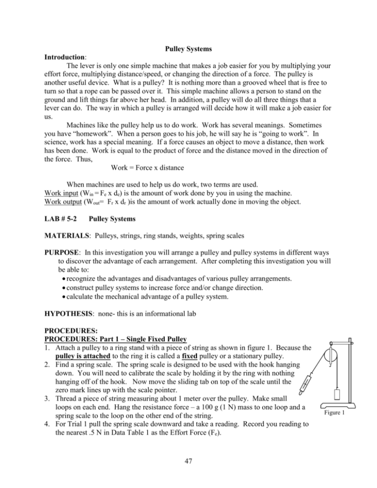
Pulley Systems Introduction: The lever is only one simple machine that makes a job easier for you by multiplying your effort force, multiplying distance/speed, or changing the direction of a force. The pulley is another useful device. What is a pulley? It is nothing more than a grooved wheel that is free to turn so that a rope can be passed over it. This simple machine allows a person to stand on the ground and lift things far above her head. In addition, a pulley will do all three things that a lever can do. The way in which a pulley is arranged will decide how it will make a job easier for us. Machines like the pulley help us to do work. Work has several meanings. Sometimes you have “homework”. When a person goes to his job, he will say he is “going to work”. In science, work has a special meaning. If a force causes an object to move a distance, then work has been done. Work is equal to the product of force and the distance moved in the direction of the force. Thus, Work = Force x distance When machines are used to help us do work, two terms are used. Work input (Win = Fe x de) is the amount of work done by you in using the machine. Work output (Wout= Fr x dr )is the amount of work actually done in moving the object. LAB # 5-2 Pulley Systems MATERIALS: Pulleys, strings, ring stands, weights, spring scales PURPOSE: In this investigation you will arrange a pulley and pulley systems in different ways to discover the advantage of each arrangement. After completing this investigation you will be able to: recognize the advantages and disadvantages of various pulley arrangements. construct pulley systems to increase force and/or change direction. calculate the mechanical advantage of a pulley system. HYPOTHESIS: none- this is an informational lab PROCEDURES: PROCEDURES: Part 1 – Single Fixed Pulley 1. Attach a pulley to a ring stand with a piece of string as shown in figure 1. Because the pulley is attached to the ring it is called a fixed pulley or a stationary pulley. 2. Find a spring scale. The spring scale is designed to be used with the hook hanging down. You will need to calibrate the scale by holding it by the ring with nothing hanging off of the hook. Now move the sliding tab on top of the scale until the zero mark lines up with the scale pointer. 3. Thread a piece of string measuring about 1 meter over the pulley. Make small loops on each end. Hang the resistance force – a 100 g (1 N) mass to one loop and a spring scale to the loop on the other end of the string. 4. For Trial 1 pull the spring scale downward and take a reading. Record you reading to the nearest .5 N in Data Table 1 as the Effort Force (Fe). 47 Figure 1 5. To determine the effort distance (de) for Trial 1, measure the vertical distance you move down as the resistance moves up .10 m. Record de in Data Table 1. 6. For Trial 2 add another 100 g mass to give a resistance force (Fr) of approximately 2 N. Measure the effort force and effort distance as you did in Trial 1 and record your readings in Data Table 1. Note how the resistance distance changes with each trial. 7. For Trial 3, add another 100 g to give a 3 N resistance force. Again, measure the effort force and effort distance and record your readings in Data Table 1. 8. Use the data from Data Table 1 to calculate the work input and work output of the single fixed pulley. Record your answers in Data Table 2. Use the standard Win and Wout formulae found in the introduction. 9. Calculate the mechanical advantage of the single fixed pulley for each trial and record this in Data Table 2. Use the formula Ideal MA = de / dr. DATA TABLE 1 –Single Fixed Pulley Effort Force (Fe) Effort Distance (de) DATA TABLE 2 – Single Fixed Pulley: Work & MA Work Work Trial output Input (Wout) (Win) Trial Resistance Force (Fr) Resistance Distance (dr) 1 1N .10 m _____N _____m 1 _______Nm _______Nm 2 2N .15 m _____N _____m 2 _______Nm _______Nm 3 3N .20 m _____N _____m 3 _______Nm _______Nm QUESTIONS: Part 1-Single Fixed Pulley 1. How did the effort force compare to the resistance force in each trial? a. Fe < Fr b. Fe > Fr c. Fe = Fr 2. How did work input compare to work output for the 3 trials? a. Win < Wout b. Win > Wout c. Win = Wout 3. Compare the mechanical advantage in the 3 trials. a. MA increased b. MA decreased c. MA remained equal 4. What kind of help or advantage does a single fixed pulley provide? (choose one) a. Multiplies effort force b. multiplies distance/speed c. changes direction 5. Name 3 places you might find a single fixed pulley (other than science class). 48 MA PROCEDURE Part 2 – Single Moveable Pulley 1. Arrange the pulley as shown in Figure 2. Notice that the pulley is free to move and is not attached to the ring stand. Therefore, it is called a moveable pulley. Be sure that the scale is zeroed. 2. Fasten the 100 g mass (1 N) directly to the pulley. 3. Pull the spring scale in an upward vertical direction. In Data Table 3, record the reading in the effort force (Fe) column to the nearest .5 N. Figure 2 4. Measure the vertical distance (in meters) your effort moves when the resistance force moves a vertical distance of .10 m. Record the effort distance (de) in Data Table 3. 5. Repeat steps 2 and 3 using the resistance forces and resistance distances listed for Trials 2 and 3 in Data Table 3. 6. Using the Win, Wout , and MA formulae, calculate the values for work input, work output and ideal mechanical advantage for each of the three trials. Record the answers in Data Table 4. DATA TABLE 3: Single Moveable Pulley Resistance Effort ForceEffort Distance Distance (Fe) (de) (dr) DATA TABLE 4: Single Moveable Pulley Work & MA Work Work output Trial Input MA (Wout) (Win) Trial Resistance Force (Fr) 1 1N .10 m _____N _____m 1 _______Nm _______Nm 2 2N .15 m _____N _____m 2 _______Nm _______Nm 3 3N .20 m _____N _____m 3 _______Nm _______Nm QUESTIONS: Part 2-Single Moveable Pulley 1. How did the effort force compare to the resistance force in each trial? a. Fe < Fr b. Fe > Fr c. Fe = Fr 2. How did work input compare to work output for the 3 trials? a. Win < Wout b. Win > Wout c. Win = Wout 3. Compare the mechanical advantage in the 3 trials. a. MA increased b. MA decreased c. MA remained equal 4. What kind of help or advantage does a single moveable pulley provide? (choose one) a. Multiplies effort force b. multiplies distance/speed c. changes direction 5. Name 1 place you might find a single moveable pulley (other than science class). Multiple Pulley Systems Pulleys can be arranged to give a greater mechanical advantage than those you have been using so that heavier weights can be lifted. In order to do so, several pulleys must be used together and connected in certain ways. In this part of the investigation, you will be using combinations of single fixed, single movable, double fixed and double movable pulleys. You will be connecting them in different ways and finding the mechanical advantage of each combination. 49 PROCEDURE: Part 3 – Multiple Pulley Systems 1. Arrange the pulleys as shown in systems A, B, C, and D and record the data collected in Data Table 5. 2. For each system, measure the effort force needed to lift a 5 N (500 g) resistance force. A B C D 3. Measure how far the effort force of each system must move to raise the weight a distance of .10 m. 4. Calculate the ideal mechanical advantage of each system and record in Data Table 5. 5. Count the number of strings that support the weight in each of the four systems. DATA TABLE 5: Pulley Systems System Resistance Force (Fr) Resistance Distance (dr) Effort Force (Fe) Effort Distance (de) A 5N .10 m _____N _____m B 5N .10 m _____N _____m C 5N .10 m _____N _____m D 5N .10 m _____N _____m # of support strings MA QUESTIONS: Part 3 – Pulley Systems 1. The MA of system A is (<, >, =) the MA of system B. 2. The MA of system B is (<, >, =) the MA of system C. 3. The MA of system C is (<, >, =) the MA of system D. 4. What happened to the MA as the difference between de and dr increased? a. MA increases b. MA decreases c. MA stays the same 5. What is the relationship between mechanical advantage and the number of supporting strings? 6. Study the pulley systems X, Y, & Z. Predict the MA of each of the pulley systems by using the number of support strings. a. MA of system X = ____________ b. MA of system Y = ____________ c. MA of system Z = ____________ 7. Draw a pulley system with a MA = 6 that pulls down. ANALYSIS & REFLECTION: X 50 Y Z
