Paper - engine
advertisement
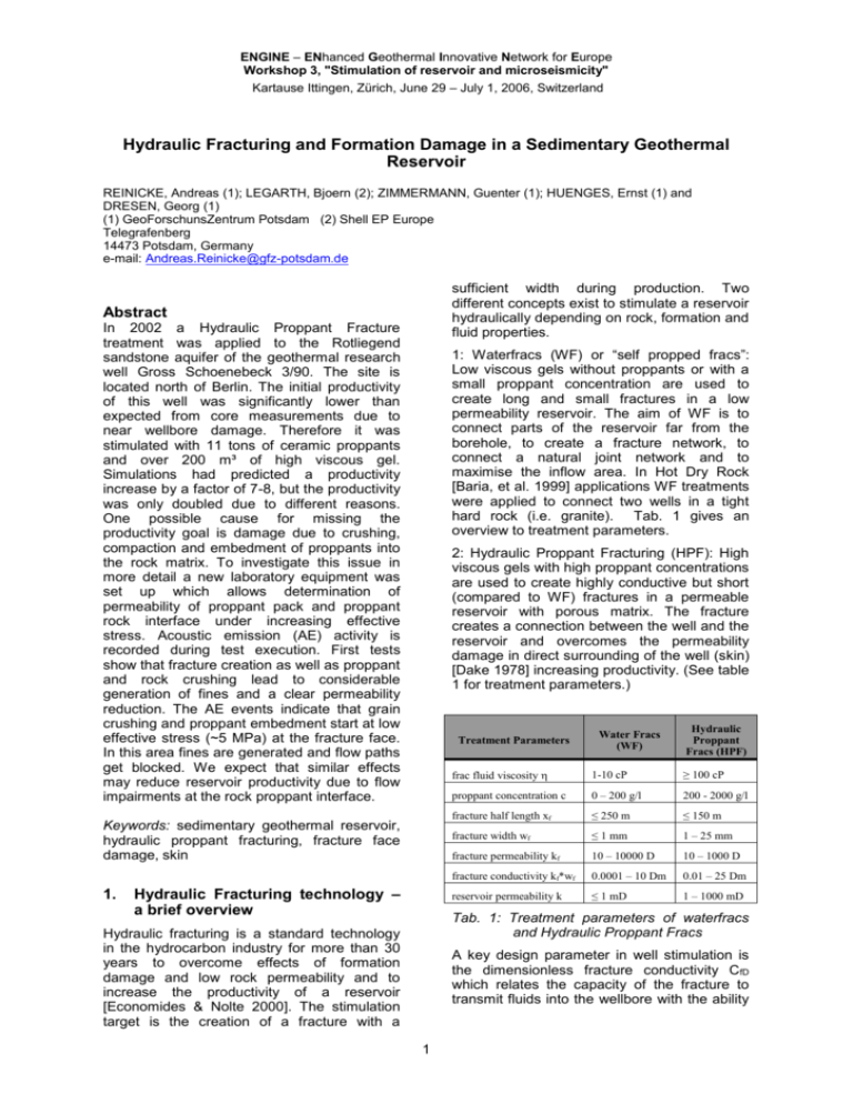
ENGINE – ENhanced Geothermal Innovative Network for Europe Workshop 3, "Stimulation of reservoir and microseismicity" Kartause Ittingen, Zürich, June 29 – July 1, 2006, Switzerland Hydraulic Fracturing and Formation Damage in a Sedimentary Geothermal Reservoir REINICKE, Andreas (1); LEGARTH, Bjoern (2); ZIMMERMANN, Guenter (1); HUENGES, Ernst (1) and DRESEN, Georg (1) (1) GeoForschunsZentrum Potsdam (2) Shell EP Europe Telegrafenberg 14473 Potsdam, Germany e-mail: Andreas.Reinicke@gfz-potsdam.de sufficient width during production. Two different concepts exist to stimulate a reservoir hydraulically depending on rock, formation and fluid properties. Abstract In 2002 a Hydraulic Proppant Fracture treatment was applied to the Rotliegend sandstone aquifer of the geothermal research well Gross Schoenebeck 3/90. The site is located north of Berlin. The initial productivity of this well was significantly lower than expected from core measurements due to near wellbore damage. Therefore it was stimulated with 11 tons of ceramic proppants and over 200 m³ of high viscous gel. Simulations had predicted a productivity increase by a factor of 7-8, but the productivity was only doubled due to different reasons. One possible cause for missing the productivity goal is damage due to crushing, compaction and embedment of proppants into the rock matrix. To investigate this issue in more detail a new laboratory equipment was set up which allows determination of permeability of proppant pack and proppant rock interface under increasing effective stress. Acoustic emission (AE) activity is recorded during test execution. First tests show that fracture creation as well as proppant and rock crushing lead to considerable generation of fines and a clear permeability reduction. The AE events indicate that grain crushing and proppant embedment start at low effective stress (~5 MPa) at the fracture face. In this area fines are generated and flow paths get blocked. We expect that similar effects may reduce reservoir productivity due to flow impairments at the rock proppant interface. 1: Waterfracs (WF) or “self propped fracs”: Low viscous gels without proppants or with a small proppant concentration are used to create long and small fractures in a low permeability reservoir. The aim of WF is to connect parts of the reservoir far from the borehole, to create a fracture network, to connect a natural joint network and to maximise the inflow area. In Hot Dry Rock [Baria, et al. 1999] applications WF treatments were applied to connect two wells in a tight hard rock (i.e. granite). Tab. 1 gives an overview to treatment parameters. 2: Hydraulic Proppant Fracturing (HPF): High viscous gels with high proppant concentrations are used to create highly conductive but short (compared to WF) fractures in a permeable reservoir with porous matrix. The fracture creates a connection between the well and the reservoir and overcomes the permeability damage in direct surrounding of the well (skin) [Dake 1978] increasing productivity. (See table 1 for treatment parameters.) Treatment Parameters Keywords: sedimentary geothermal reservoir, hydraulic proppant fracturing, fracture face damage, skin 1. Hydraulic Fracturing technology – a brief overview Water Fracs (WF) Hydraulic Proppant Fracs (HPF) frac fluid viscosity 1-10 cP ≥ 100 cP proppant concentration c 0 – 200 g/l 200 - 2000 g/l fracture half length xf ≤ 250 m ≤ 150 m fracture width wf ≤ 1 mm 1 – 25 mm fracture permeability kf 10 – 10000 D 10 – 1000 D fracture conductivity kf*wf 0.0001 – 10 Dm 0.01 – 25 Dm reservoir permeability k ≤ 1 mD 1 – 1000 mD Tab. 1: Treatment parameters of waterfracs and Hydraulic Proppant Fracs Hydraulic fracturing is a standard technology in the hydrocarbon industry for more than 30 years to overcome effects of formation damage and low rock permeability and to increase the productivity of a reservoir [Economides & Nolte 2000]. The stimulation target is the creation of a fracture with a A key design parameter in well stimulation is the dimensionless fracture conductivity CfD which relates the capacity of the fracture to transmit fluids into the wellbore with the ability 1 of the formation to deliver fluid into the fracture [Economides & Nolte 2000]. C fD k f wf xf k northeast of Berlin in the North-German Basin with formation fluids of 150 °C and porosities of up to 10 % [Zimmermann, et al. 2005]. The well is drilled through a series of Rotliegend sediments consisting of silt-, sandstones and conglomerate into vulcanite layers with 400 m open-hole section at the bottom Eq. 1 For steady state conditions the optimum CfD is 1, but in reality CfD should be around 10 to guarantee good drainage during transient flow periods [Economides & Nolte 2000]. To reach this design goal a high conductivity contrast between fracture and formation is necessary. The initial productivity of the well was significantly lower than expected from core measurements and logs. Drilling operations produced a significant near wellbore damage resulting in a low productivity. Therefore, two HPF open hole treatments in the Rotliegend sandstones were conducted to bypass the skin zone and to connect undamaged reservoir regions. Since core and log measurements indicate reservoir permeabilities between 10 and 150 mD, a WF treatment was not applicable if a high CfD should be achieved. In addition there exists no experience with WF treatments in sedimentary geothermal reservoirs. The advantage of WF compared to HPF is a reduction of costs - costs for material are lower and realisation of these stimulations is easier. In addition the permeability of WF could be 10 – 100 times higher than permeabilities from HPF. Different studies have shown [Mayerhofer & Meehan 1998, Fredd, et al. 2001] that the field of application is limited to reservoirs with small permeability (< 1 mD). In these reservoirs it’s important to maximise the inflow area for the slow diffusion process of fluid flow through the tight rock matrix. And due to low formation permeability and big fracture half length CfD ≥ 10 could be realised although width of self propped fracs is small. The success of the stimulation is dependent on the self propping potential of the reservoir rock. The self propping potential includes the shear potential of the formation as well as the toughness of the rock and a residual fracture width due to flushed particles. Consequently, a successful treatment depends on parameters that are difficult to manage. In contrast HPF treatments allow a good control of stimulation parameters. The properties of the fracture can be predicted and optimised. With special Tip Screen Out (TSO) [Economides & Nolte 2000] design widths up to 25 mm are possible. Thus, a wide range of formations with respect to permeability can be treated using this technology. Stimulation parameters could be optimised for a certain reservoir to get a sufficient CfD. But there more expensive and frac gels must be carefully selected to avoid damage due to chemical precipitations and gel residues. 2. Fig.1) Hydraulic stimulation treatments in the geothermal research well Gross Schoenebeck 3/90 Lithology- and temperature-profile of the well Groß Schoenebeck 3/90 The test interval was isolated with a sand plug at the bottom of the well and with a mechanical packer at the top. About 200 m³ of high viscosity fluid (polymers) with 11 tons of proppants were used for the well stimulation in two intervals. Since stimulation operations are accomplished in the open hole section under high temperature, a less aggressive frac design was applied to avoid a by-pass of the packer [Legarth, et al. 2005a]. Enhanced productivity of thermal water is necessary for the economic and sustainable generation of geothermal electricity. This requires a sufficiently high reservoir temperature (above 120 °C) and a high production rate of the deep fluids of at least 50 m³/h. An adequate temperature profile for this purpose is found in the former gas exploration well Groß Schoenebeck 3/90, about 80 km 2 clean-up after the treatment, geochemical alterations due to infiltration processes and precipitation, 2) mechanical damages like proppant pack failure. Especially in high stress and high temperature environments proppant crushing is an issue, 3) an additional damage mechanism results from a mechanically induced fracture face skin (FFS) between fracture and rock matrix. The general idea is that proppant embedment and grain/proppant crushing lead to a reduced permeability in the fracture face and during the production out of the reservoir this zone acts as a filter and the FFS zone grows into the formation. Before and after stimulation production tests (casing lift tests with nitrogen) were performed to determine the stimulation effect. Fig. 2 displays a comparison of the flow log before and after the treatments. Before well stimulation no response in the Rotliegend sections above 4225 m could be seen, only at the transition zone between the conglomerates and the volcanic rock an inflow over 25 m is visible. After stimulation the flow log shows a response to a depth up to 4100 m indicating that the Rotliegend sandstones could be activated. The stimulation effect was estimated by analytical modelling with the FRACPROTM - a 3D fracture simulator. From modelling the theoretically achievable Fold Of Increase (FOI) is determined. The FOI is the ration between the initial reservoir productivity and the reservoir productivity after the stimulation treatment. For given fracture dimensions values for the FOI between 7 and 8 were expected. The fracture face skin is referred to as impairment affecting flow normal to the fracture surface [Cinco-Ley & Samaniego 1977]. This damage of reservoir permeability can be caused by polymer leakoff and fluid saturation changes [Adegbola & Boney 2002]. Another damaging mechanism is a reduction in relative permeability changes generated by phase changes [Holditch 1979, Romero et al. 2003]. Furthermore various laboratory, field and theoretical studies address the field of fracture damage mechanisms [i.e. Meyn 1998, Fredd, et al. 2001]. Although there exist fracture face skin models mechanical effects have not yet been taken into account. Fig. 3 presents a view of the proppant rock matrix interface in a fracture. Under increasing effective closure stress grains and proppants get crushed and embedded and this leads to a compacted band in the fracture face. This effect is amplified by migration and deposition of fines from the formation into the damaged zone. The flow path becomes more tortuous and this results in a lower permeability at the fracture face. 4050 depth [m] 4100 4150 4200 4250 08.01.2001 - before sandstone stimulation A laboratory equipment was set up which allows determination of permeability development of the proppant pack and proppant rock interface under increasing effective stress. Fig. 4 gives a schematic view of this setup. A core with 50 mm diameter, and fractured in the middle and filled with proppants simulating a propped fracture in the reservoir. During an experiment a constant confining stress Pc is applied and the axial load is increased simulating increasing stress on proppant pack during draw down. 25.02.2002 - after sandstone stimulation 0 5 10 15 20 25 30 cumulative flow [m³/h] Fig. 2) Cumulative flow measured with a flowmeter during short term lift tests to obtain the inflow zones But post-frac productivity was considerable lower than expected and a FOI of only 1.8 was reached. The modelling with FRACPROTM as well as the planning, execution and evaluation of the stimulation experiments is extensively explained by [Legarth, et al. 2005a, Legarth 2003]. 3. Permeability is measured in axial direction to investigate the effects of a mechanical FFS. Acoustic Emission (AE) activity is recorded continuously to locate the damaging events. Mechanical induced fracture face skin Treatment failure could be very often attributed to fracture damage processes like: 1) poor 3 into the proppant pack. Microscopic investigations after reopening the fracture show crushed proppants as well as crushed grains. Fines generated from quartz grains were detected in the proppant pack. Fig. 3) Rock matrix proppant contact of a propped fracture. Proppant embedment and grain / proppant crushing leads to a reduced permeability in the fracture face. Modified from [Legarth, et al. 2005b]. 1 [MPa] Axial stress 3 [MPa] Conf. pressure A test is divided into 3 steps: 1) The mechanical properties of intact rock sample are determined and initial permeability is measured. 2) A 3-Point-Bending-test is applied creating a tensile fracture comparable to a hydraulic fracture. 3) The fracture is opened carefully, filled with 2 lb/ft² (~ 10 kg/m²) of intermediated strength proppants with a 20/40 mesh and closed aligned. The proppant concentration results in a 5 mm proppant bed with 6-7 layers. The setup is arranged as shown in Fig. 4 including the cups for the AE sensors. PP [bar] Pore pressure Qi [ml/min] Flow rate Fig. 4) Experimental setup for determination of the hydraulic permeability of the Fracture Face Skin zone (FFS) zone. Permeability during axial loading is measured, proppant and grain crushing is recorded with AE sensors From the width of the cloud of AE-events the thickness of the damaged zone (L2) could be estimated to 4 mm. With the knowledge of the measured initial permeability an estimation of the permeability of the FFS is possible. Proppant pack permeability was assumed as infinite. It is considerable higher (260 D at 50 MPa) than the rest of the system. Fig. 6 shows the recorded AE events, the AE density (projected into the zy-plane) as well as the permeability at defined effective stress levels, respectively. For this test Bentheim sandstone was used. This is a quartz rich sandstone with 95 % quartz, 3% kaolinite and 2% feldspar. The porosity is about 23 % [Klein, et al. 2001]. The Bentheim sandstone contains a small the amount of initial fines and only newly created fines will influence the permeability. A high permeability contrast between matrix and an arising FFS is expected. The setup is approximated as a series connection of hydraulic resistors resulting in following equation for the FFS permeability k 2: k2 k t k1L 2 Eq. 2 L t k1 k t L 2 k t Lt is the length of the whole sample and L1 is the lengths of the rock halves. With this formula a k2 about 4 mD is calculated. That means the permeability in the FFS is reduced by a factor of 300 compared to the initial permeability due to the fracturing process itself as well as proppant embedment and grain crushing. Fig. 5 shows a proppant imprint into the rock matrix. The grains at the contact point are completely crushed and compacted. These imprints as indicator for proppant embedment can be identified over the whole fracture face. The initial permeability (k 1) at effective stresses (eff) of 5-50 MPa is about 1250 mD and shows only minor changes over the stress interval. Already at eff of 5 MPa the permeability is reduced by a factor of 10 to 125 mD (kt). This demonstrates that the fracture face is initially damaged due to fracturing. The AE events indicate that grain crushing and proppant embedment start at low eff at the fracture face proppant contact. At high eff a further reduction in permeability to 105 mD is observed. At this stress level the main AE activity moves from the fracture face 4 Baria, R., Baumgärtner, J., Rummel, F., Pine, R.J. and Sato, Y. (1999): HDR/HWR reservoirs: concepts, understanding and creation, Geothermics 28 Cinco-Ley, H. and Samaniego, V.F. (1977): Effect of Wellbore Storage and Damage on the Transient Pressure Behaviour of Vertically Fractured Wells, SPE 6752 Dake, L.P. (1978): Fundamentals of Reservoir Engineering, Elsevier Scientific Publishing Company, Developments in Petroleum Science, Vol. 8, Netherlands Fig. 5) Proppant imprint (embedment) into the rock matrix. The grains at contact of proppant and rock are completely crushed and compacted. 4. Economides, M.J. and Nolte, K.,G. (2000): Reservoir Stimulation, 3rd Edition, Wiley and Sons Ltd., United Kingdom Fredd, C.N., McConnell, S.B. and Boney, C.L., England, K.W. (2001): Experimental Study of Fracture Conductivity for Water-Fracturing and Conventional Fracturing Applications, SPE 74138 Conclusion The open hole hydraulic proppant fracture treatments were successful applied at the geothermal research well Gross Schoenebeck 3/90. Propped fractures were created and the inflow performance of the well was enhanced. But desired post-frac productivity could not be achieved. Holditch, S.A. (1979): Factors Affecting Water Blocking and Gas Flow from Hydraulically Fractured Gas Wells, JPT, p. 1515-1524 Klein, E., Baud, P., Reuschle, T. and Wong, T.-f. (2001): Mechanical Behaviour and Failure of Bentheim Sandstone Under Triaxial Compression, Phys. Chem. Earth, Vol. 26. No. 1-2, pp. 21-25 Treatment failure is very often caused by fracture damage processes, as reported in a wide range of literature. A possible damaging effect is a mechanically induced fracture face skin caused by rock matrix proppant interactions. A first test indicates that drastic reduction of sample permeability due to fracture creation as well as proppant embedment and proppant/grain crushing can be observed. The crushing of grains and/or proppants starts at low stress (~5 MPa). The AE events are concentrated at the fracture face and there moving into the proppant pack with increasing differential stress. Crushed rock particles (fines) were mobilized and transported into the proppant pack, embedment was identified. Legarth, B. (2003); Erschließung sedimentärer Speichergesteine für eine geothermische Stromerzeugung, Dissertation, Scientific Technical Report 03/09, GeoForschungsZentrum Potsdam, Deutschland Legarth, B., Huenges, E. and Zimmermann, G. (2005a) Hydraulic Fracturing in Sedimentary Geothermal Reservoirs: Results and Implications, Int. Journal of Rock Mech., Vol. 42 p. 1028–1041 Legarth, B., Raab, S. and Huenges, E. (2005b): Mechanical Interactions between proppants and rock and their effect on hydraulic fracture performance, DGMKTagungsbericht 2005-1, Fachbereich Aufsuchung und Gewinnung, 28.-29. April 2005, Celle, Deutschland, pp. 275-288 The investigations represent a first approach to the analysis of mechanical interactions between proppants and rock matrix. Further tests with different rock types and a separate determination of proppant pack and fracture face permeability have to be conducted. 5. Mayerhofer, M.J. and Meehan, D.N. (1998): Waterfracs – Results from 50 Cotton Valley Wells, Proceedings, SPE 49104 References Adegbola, K. and Boney, C. (2002): Effect of Fracture Face Damage on Well productivity, SPE 73759 Meyn, V., (Editor), (1998): Investigation of Fracture Conductivity Under In Situ Conditions as a Function of Frac- and Formation Parameters, DGMK-Research Report 490, Institut für Erdöl- und Erdgasforschung, Clausthal-Zellerfeld API RP-60 (1989): API Recommended Practices for Testing High Strength Proppants in Hydraulic Fracturing Operations, API Production Dept., Dallas 5 (2005): Well test analysis after massive waterfrac treatments in a sedimentary geothermal reservoir, Proceedings World Geothermal Congress 2005, Turkey Romero, D.J., Valkó, P.P. and Economides, M.J. (2003): Optimization of the Productivity Index and the Fracture Geometry of a Stimulated Well With Fracture Face and Choke Skin, SPE 81908 Zimmermann, G., Reinicke, A., Holl, H.-G., Legarth, B., Saadat, A. and Huenges, E. Effective Stress 5 MPa 20 MPa 35 MPa 50 MPa Permeability with propped fracture (kt) 125 ± 5 mD 116 ± 4 mD 112 ± 4 mD 105 ± 3 mD Normalised AE-Density [%] Rock: Bentheim sandstone Porosity: 23% Initial Permeability (k1): 1250 mD Proppants: Carbo Lite Mesh: 20/40 Concentration: 2lbs/ft² Test data: 3 = 10 MPa Q = 50 ml/min Ø = 50 mm Fig.6) Comparison of initial permeability (k 1) of a Bentheim sandstone with permeability of the same sample with a propped fracture (kt) at 10 MPa confining pressure. The AE-Locations and AEDensity during loading of the sample with a propped fracture are displayed. Permeability is reduced by a factor of 10 to 125 mD (k t) at 5 MPa effective stress indicating that fracture face is initially damaged due to fracturing process itself. At high eff a further reduction in permeability to 105 mD is observed. The AE events indicate that grain crushing and proppant embedment start at low eff at the fracture face proppant contact. At high stress level the main AE activity moves from the fracture face into the proppant pack. 6
