Adaptive Modulation
(QPSK, QAM)
Intel in
Communications
Introduced below are the concepts of
digital modulation used in many
communication systems today.
Techniques described include
quadrature phase shift keying (QPSK)
and quadrature amplitude modulation
(QAM) and how these techniques can
be used to increase the capacity and
speed of a wireless network. These
modulation techniques are the basis of
communications for systems like cable
modems, DSL modems, CDMA, 3G,
Wi-Fi* (IEEE 802.11) and WiMAX*
(IEEE 802.16).
well as bending (diffraction) around
corners.
Carrier Waves
Amplitude shift keying (ASK) involves
increasing the amplitude (power) of
the wave in step with the digital signal
(in other words, low = 0, high = 1) and
is used in AM radio.
Radio waves are electromagnetic
waves that move at the speed of light
in a sine wave formation and can be
used to carry a message over a
distance. They can have different
frequencies which describes how fast
they are moving up and down which is
measured in cycles per second or
hertz. Carrier waves with different
frequencies have different properties.
For example, light waves are visible to
the naked eye but cannot travel
through walls. Radio waves
(especially those of lower frequency)
can penetrate walls and buildings as
0
1
Modulation
Modulation is the process by which a
carrier wave is able to carry the
message or digital signal (series of
ones and zeroes). There are three
basic methods to this: amplitude,
frequency and phase shift keying.
Higher orders of modulation allow us
to encode more bits per symbol or
period (time).
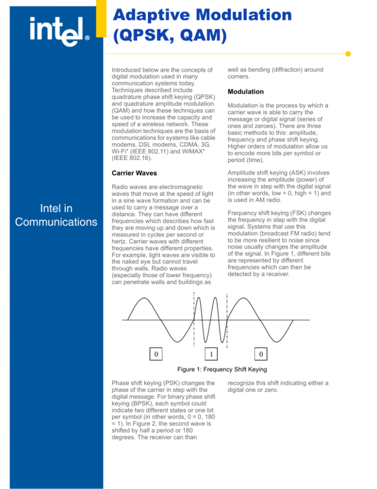
Frequency shift keying (FSK) changes
the frequency in step with the digital
signal. Systems that use this
modulation (broadcast FM radio) tend
to be more resilient to noise since
noise usually changes the amplitude
of the signal. In Figure 1, different bits
are represented by different
frequencies which can then be
detected by a receiver.
0
Figure 1: Frequency Shift Keying
Phase shift keying (PSK) changes the
phase of the carrier in step with the
digital message. For binary phase shift
keying (BPSK), each symbol could
indicate two different states or one bit
per symbol (in other words, 0 = 0, 180
= 1). In Figure 2, the second wave is
shifted by half a period or 180
degrees. The receiver can than
recognize this shift indicating either a
digital one or zero.
Adaptive Modulation (QPSK, QAM)
Application Note
1 Cycle—
Phase 0 degrees
1 Cycle—
Phase 180 degrees
Figure 2: Phase Shift Keying
phase shift (0 degrees), the bits “00” are
represented. If there is a phase shift of 180
degrees, the bits “11” are represented.
QPSK adds two more phases: 90 and 270
degrees. Now two symbols per bit can be
transmitted. Each symbol’s phase is compared
relative to the previous symbol; so, if there is no
Phase Shift 90 degrees
Phase Shift 0 degrees
“01”
“00”
Figure 3: Quadrature Phase Shift Keying
Table 1: Quadrature Phase Shift Keying
Symbol
Phase Shift
00
0 degrees
01
90 degrees
11
180 degrees
10
270 degrees
ASK and PSK can be combined to create QAM
where both the phase and amplitude are changed.
The receiver then receives this modulated signal,
detects the shifts and demodulates the signal back
into the original data stream. In Figure 4 showing
16-QAM, each symbol can now represent four bits
instead of just the two bits per symbol with QPSK.
Each point indicates a unique amplitude and
phase of the wave (for example, point (1,1)
indicates 90 degrees and amplitude of 1).
Amplitude
Application Note
Adaptive Modulation (QPSK, QAM)
0010
0110
0011
0111
3
1
1110
1010
1111
1011
0000
0
-3
-1
0001
0101
0000
0100
1
3
1101
1001
1100
1000
-1
-3
Phase
Figure 4: Quadrature Amplitude Modulation 16-QAM
Adaptive Modulation
Different order modulations allow you to send
more bits per symbol and thus achieve higher
throughputs or better spectral efficiencies.
However, it must also be noted that when using a
modulation technique such as 64-QAM, better
signal-to-noise ratios (SNRs) are needed to
overcome any interference and maintain a certain
bit error ratio (BER).
The use of adaptive modulation allows a wireless
system to choose the highest order modulation
depending on the channel conditions. In Figure 5,
you can see a general estimate of the channel
conditions needed for different modulation
techniques. As you increase your range, you step
down to lower modulations (in other words,
BPSK), but as you are closer you can utilize higher
order modulations like QAM for increased
throughput. In addition, adaptive modulation
allows the system to overcome fading and other
interference.
Adaptive Modulation (QPSK, QAM)
Application Note
Figure 5: Adaptive Modulation and Coding
Both QAM and QPSK are modulation techniques
used in IEEE 802.11 (Wi-Fi*), IEEE 802.16
(WiMAX*) and 3G (WCDMA/HSDPA) wireless
technologies. The modulated signals are then
demodulated at the receiver where the original
digital message can be recovered. The use of
adaptive modulation allows wireless technologies
to optimize throughput, yielding higher throughputs
while also covering long distances.
Author Biography
Communications Group. Since joining Intel in
2000, he has worked on a variety of projects,
including chipset design, chipset architecture,
strategic marketing and several wireless
technologies including: BLUETOOTH*, Wi-Fi*
(IEEE 802.11), ultra wideband, WiMAX* (802.16)
and 3G. He is currently researching future wireless
technologies for mobility/portability including
WiMAX*, 3G and beyond. He holds a B.S. in
computer engineering from the University of
Kansas.
Sam W. Ho is a technical marketing engineer in
the Wireless Networking Group, part of the Intel
Intel Access
WiMAX* - Broadband Wireless Access Technology:
www.intel.com/netcomms/technologies/wimax/index.htm
Other Intel Support:
Intel Literature Center developer.intel.com/design/litcentr/
(800) 548-4725 7 a.m. to 7 p.m. CST (U.S. and Canada)
General Information Hotline:
(800) 628-8686 or (916) 356-3104 5 a.m. to 5 p.m. PST
International locations please contact your local sales office.
For more information, visit the Intel Web site at: developer.intel.com
INFORMATION IN THIS DOCUMENT IS PROVIDED IN CONNECTION WITH INTEL® PRODUCTS. NO LICENSE, EXPRESS OR IMPLIED, BY ESTOPPEL OR OTHERWISE,
TO ANY INTELLECTUAL PROPERTY RIGHTS IS GRANTED BY THIS DOCUMENT. EXCEPT AS PROVIDED IN INTEL'S TERMS AND CONDITIONS OF SALE FOR SUCH
PRODUCTS, INTEL ASSUMES NO LIABILITY WHATSOEVER, AND INTEL DISCLAIMS ANY EXPRESS OR IMPLIED WARRANTY, RELATING TO SALE AND/OR USE OF
INTEL PRODUCTS INCLUDING LIABILITY OR WARRANTIES RELATING TO FITNESS FOR A PARTICULAR PURPOSE, MERCHANTABILITY, OR INFRINGEMENT OF
ANY PATENT, COPYRIGHT OR OTHER INTELLECTUAL PROPERTY RIGHT. Intel products are not intended for use in medical, life saving, or life sustaining applications. Intel
may make changes to specifications and product descriptions at any time, without notice.
* Other names and brands may be claimed as the property of others.
Copyright © 2004, Intel Corporation. All rights reserved.
Intel and the Intel logo are trademarks or registered trademarks of Intel Corporation or its subsidiaries in the United States and other countries.
Printed in USA.
Please Recycle
Order Number 303788-001

