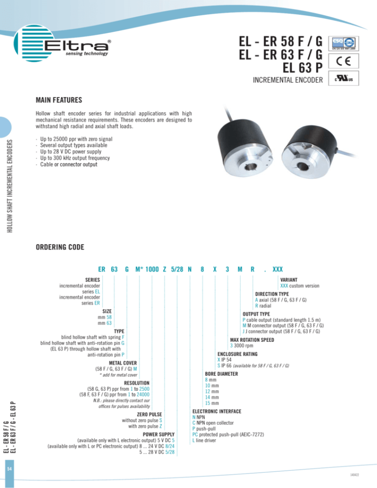
EL - ER 58 F / G
EL - ER 63 F / G
EL 63 P
INCREMENTAL ENCODER
MAIN FEATURES
HOLLOW SHAFT INCREMENTAL ENCODERS
Hollow shaft encoder series for industrial applications with high
mechanical resistance requirements. These encoders are designed to
withstand high radial and axial shaft loads.
·
·
·
·
·
Up to 25000 ppr with zero signal
Several output types available
Up to 28 V DC power supply
Up to 300 kHz output frequency
Cable or connector output
ORDERING CODE
ER 63 G M* 1000 Z 5/28 N
8
X
3
M
SERIES
incremental encoder
series EL
incremental encoder
series ER
. XXX
VARIANT
XXX custom version
DIRECTION TYPE
A axial (58 F / G, 63 F / G)
R radial
SIZE
mm 58
mm 63
TYPE
blind hollow shaft with spring F
blind hollow shaft with anti-rotation pin G
(EL 63 P) through hollow shaft with
anti-rotation pin P
METAL COVER
(58 F / G, 63 F / G) M
* add for metal cover
RESOLUTION
(58 G, 63 P) ppr from 1 to 2500
(58 F, 63 F / G) ppr from 1 to 24000
EL - ER 58 F / G
EL - ER 63 F / G - EL 63 P
R
N.B.: please directly contact our
offices for pulses availability
ZERO PULSE
without zero pulse S
with zero pulse Z
POWER SUPPLY
(available only with L electronic output) 5 V DC 5
(available only with L or PC electronic output) 8 ... 24 V DC 8/24
5 ... 28 V DC 5/28
OUTPUT TYPE
P cable output (standard length 1.5 m)
M M connector output (58 F / G, 63 F / G)
J J connector output (58 F / G, 63 F / G)
MAX ROTATION SPEED
3 3000 rpm
ENCLOSURE RATING
X IP 54
S IP 66 (available for 58 F / G, 63 F / G)
BORE DIAMETER
8 mm
10 mm
12 mm
14 mm
15 mm
ELECTRONIC INTERFACE
N NPN
C NPN open collector
P push-pull
PC protected push-pull (AEIC-7272)
L line driver
54
140422
EL - ER 63 F / G
EL - ER 58 F / G
MOD&
MOD&
%3!
MOD'
MOD&
MAX
BORE(
MOD'
HOLLOW SHAFT INCREMENTAL ENCODERS
MAX
MAX
MAX
BORE(
MOD'
MOD&
MOD'
EL 63 P
EL 58 F, EL 63 F mounting instructions
1.
2.
3.
4.
5.
Couple encoder shaft with motor shaft
Fix spring to motor flange without tightening it
Fix encoder shaft on motor shaft
Turn encoder for electrical adjustment (phasing)
Fix spring
EL 58 G, EL 63 G, EL 63 P mounting instructions
3.
Fix anti-rotation pin on motor flange
Couple encoder shaft with motor shaft, making sure pin
is inserted in the hole on the front part of the encoder
(maintaining a minimum distance of 0.5 mm).
Fix encoder shaft on motor shaft
BORE(
1.
2.
EL - ER 58 F / G
EL - ER 63 F / G - EL 63 P
%3!
-
www.eltra.it - eltra@eltra.it
140422
© Copyright 2014 Eltra S.p.a. Unipersonale. All rights reserved. All informations in this catalog are subject to change without notice.
Eltra takes no responsibility for typographic errors. For the terms of sales please check the website www.eltra.it.
55
Dimensions with metal
cover axial output
MAX
Electrical specifications
HOLLOW SHAFT INCREMENTAL ENCODERS
MAX
MAX
Dimensions with metal
cover radial output
Mechanical specifications
Shaft diameter ø 8 / 10 / 12 / 14 / 15 mm
1 to 2500 ppr (EL 58 G, EL 63 P)
Resolution from
from 1 to 24000 ppr (EL 58 F, EL 63 F / G)
5 V DC ± 10%
Power supply 5 ... 28 V DC ± 5%
8 ... 24 V DC ± 5% (reverse polarity protection)
Enclosure rating
IP 54 (IEC 60529)
IP 66 (available for 58 F / G, 63 F / G) (IEC 60529)
Max rotation speed 3000 rpm
Max shaft load 200 N (20 kp)
Power draw
without load 800 mW
G, 11 ms up to 2500 ppr (IEC 60068-2-27)
Shock 50
20 G, 11 ms from 3000 ppr (IEC 60068-2-27)
mA for channel
Max load current 50
20 mA for channel (line driver)
Vibration 10 G, 10 ... 2000 Hz (IEC 60068-2-6)
/ NPN open collector /
Output type NPN
push-pull / line driver
Body material EN-AW 2011 aluminum
Shaft material 1.4305 / AISI 303 stainless steel
Max output 300 kHz
frequency
Housing material PA 66 glass fiber reinforced / painted aluminum
Bearings 2 ball bearings
Counting direction A leads B clockwise (shaft view)
Bearings life 109 revolutions
Electromagnetic IEC 61000-6-2
compatibility IEC 61000-6-4
Operating -10° ... +60°C EL series
temperature -20° ... +70°C ER series
ER series resolutions
100 - 120 - 128 - 150 - 200 - 240 - 250 - 256 - 300 - 360 - 400 - 480
- 500 - 512 - 600 - 625 - 720 - 750 - 800 - 900 - 1000 - 1024 - 1200 - 1250
- 1440 - 1500 - 1600 - 1800 - 2000 - 2048 - 2500
Storage
temperature -25° ... +70°C
Weight 350 g
EL series resolutions
1 - 2 - 4 - 5 - 10 - 15 - 16 - 20 - 25 - 30 - 32 - 40 - 50 - 60 - 70 - 80 - 90
- 160 - 180 - 350 - 450 - 660 - 700 - 3000 - 3600 - 4000 - 4096 5000 - 6000 - 7200 - 8000 - 8192 - 9000 - 10000 - 10240 - 12000
- 14400 - 16000 - 16384 - 18000 - 20000 - 20480 - 24000
EL - ER 58 F / G
EL - ER 63 F / G - EL 63 P
Connections
Function
N/C/P
cable output
Line driver
cable output
Output J7
N/C/P
+V DC
0V
Ch. A
Ch. ACh. B
Ch. BCh. Z
Ch. Z-
red
black
green
/
yellow
/
blue
/
shield
red
black
green
brown
yellow
orange
blue
white
shield
6
1
3
/
5
/
4
/
7
Output J7
Line Driver
without Zero
4
6
1
3
2
5
/
/
7
Output M7
N/C/P
F
A
C
/
E
/
D
/
G
Output M7
Line Driver
without Zero
D
F
A
C
B
E
/
/
G
Output J10
Line Driver
with Zero
4-5
6
1
7
2
8
3
9
10
Output M10
Line Driver
with Zero
D-E
F
A
G
B
H
C
I
J
56
140422


