Why true-rms matters
for HVAC technicians
Non-linear loads need a true-rms
test tool for accurate readings
Application Note
For today’s HVAC technician, troubleshooting
electrical problems is becoming more difficult
without the use of true rms test tools. This is
due in part to the proliferation of new solid state
adjustable speed motor drives and heating
controls containing power semiconductors or
rectifiers. These loads are referred to as “non
linear.” Non linear loads draw current in short
pulses rather than the smooth sine wave drawn
by a linear load such as an induction motor. The
current wave shape can have a drastic effect
on a test tool reading.
There are two types of electrical test tools
commonly available: “Average responding-rms
indicating” and “true-rms.” The average
responding units give correct readings for
linear loads such as induction motors, resistive
heaters, and incandescent lights.
But when loads are non-linear, average
responding meters may read anywhere from
5 % to as much as 40 % low when measuring
line side currents.
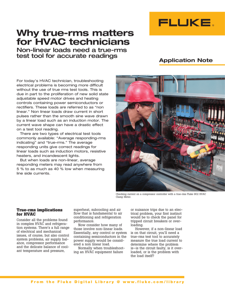
Checking current on a compressor controller with a true-rms Fluke 902 HVAC
Clamp Meter.
True-rms implications
for HVAC
Consider all the problems found
in complex HVAC and refrigeration systems. There’s a full range
of electrical and mechanical
issues, of course, but also control
system problems, air supply balance, compressor performance
and the delicate balance of coolant temperature and pressure,
superheat, subcooling and air
flow that is fundamental to air
conditioning and refrigeration
performance.
Now consider how many of
those involve non-linear loads.
Essentially, any control or system
containing semiconductors in the
power supply would be considered a non linear load.
Normally when troubleshooting an HVAC equipment failure
or nuisance trips due to an electrical problem, your first instinct
would be to check the panel for
tripped circuit breakers or overloading.
However, if a non-linear load
is on that circuit, you’ll need a
true-rms test tool to accurately
measure the true load current to
determine where the problem
is—is the circuit faulty, is it overloaded, or is the problem with
the load itself?
From the Fluke Digital Library @ www.fluke.com/library
One current—two readings. Which do you trust? The branch circuit above feeds
a non-linear load with distorted current. The true-rms clamp on the right reads
correctly but the average responding clamp reads low by 32 percent.
HVAC electrical measure- 3. Check line voltage at the
motor terminals with the comments affected by rms
Here’s a birds-eye view of the
HVAC electrical measurements
that require a true-rms test tool.
• Measuring supply side current
and voltage as well as load
side current and voltage
• Measuring current and voltage phase balance on 3 phase
systems
• Troubleshooting compressor
electrical motor faults
Troubleshooting
compressor motor faults
Compressor failures are often
caused by electrical faults. The
best tool for this measurement
sequence is a true-rms clamp
meter like the Fluke 902 or a
true rms digital multimeter with
a current clamp accessory.
1. Allow the compressor to cool
down prior to the electrical
test. This allows the device
to reset to its normal position.
Then, remove the electrical
terminal cover.
2. Check line voltage at the load
center with the compressor off.
Low line voltage causes the
motor to draw more current
than normal and may result
in overheating and premature
failure. Line voltage that is
too high will cause excessive
inrush current at motor start,
again leading to premature
failure.
pressor running. The true-rms
voltage should be within 10 %
of the motor rating.
4. Check running current. The
readings should not exceed
manufacturers’ full load rated
amps during heavy load periods. Low amps are normal
during low load conditions.
Excessive current may be due
to shorted or grounded windings, a bad capacitor, a faulty
relay, or bearing fatigue.
Troubleshooting
compressor motor failures
caused by refrigeration
system problems
Compressor electrical problems
are often caused by mechanical system failure or installation
and service errors. Compressor
bearings can fail or lock up due
to improper lubrication or insufficient oil return to the compressor
(largely due to poor piping). To
diagnose this problem, measure
the compressor current with a
true-rms test tool. The current
readings should not exceed manufacturers full load ratings. Worn
bearings will cause higher than
normal current readings.
Checking for voltage
imbalance in a three-phase
compressor motor
Voltage imbalance in threephase motors causes high currents in the motor windings.
Fluke Corporation Why true-rms matters for HVAC technicians
These higher currents generate
additional heat that degrades
and destroys winding insulation. A 10 °C rise in motor temperature can reduce motor life
by half.
Voltage unbalance is usually
caused by adding single phase
loads on the same circuit used
by the compressor, although
sometimes component failure is
the culprit. Voltage unbalance
for three phase motors shouldn’t
exceed one percent, otherwise
the motor load capacity should
be derated. To calculate voltage
unbalance, use this formula:
% Voltage Unbalance = 100 x
(maximum deviation from average) /
Average voltage
For example, given true-rms
voltages of 449, 470, and 462,
the average voltage is 460. The
maximum deviation from the
average is 11 volts. The percent
unbalance is 100 x 11 / 460 =
2.39 %. That result indicates a
voltage unbalance problem. The
closer the motor is matched to
the load, the less reserve power
it has and the more important it
becomes to periodically check
motor supply voltages.
Checking for current
unbalance in a three-phase
compressor motor
For accurate results, measure
current with a true-rms clamp
meter or true rms DMM with
a clamp attachment. The goal
behind measuring current on a
three-phase compressor motor is
to ensure that the full load rating on the motor nameplate isn’t
exceeded and to verify that all
three phases are balanced.
Unbalanced current can be
caused by voltage imbalance
between the phases, a shorted
motor winding, or a high resistance connection. To calculate
current unbalance, use the same
formula as above but substitute
current in amps. Maximum current unbalance for three-phase
motors is typically 8 % to10 %.
A 1 % voltage unbalance will
cause an 8 % current unbalance.
What is true-rms?
“RMS” stands for root-meansquare. It comes from a mathematical formula that calculates
the “effective” value (or heating
value) of any ac wave shape. In
electrical terms, the ac rms value
is equivalent to the dc heating
value of a particular waveform—
voltage or current. For example,
if a resistive heating element in
an electric furnace is rated at
15 kW of heat at 240 V ac rms,
then we would get the same
amount of heat if we applied
240 V of dc instead of ac.
From a measurement perspective, the rms value is equal to
.707 of the peak value of the
sine waveform.
+
Vrms = ?
Voltage
For example, say an ac voltage source has a positive peak
value of 165 V.*
Vrms = Vpeak x .707
Vrms = 165 x .707
Vrms = 116.655 V
RMS voltage conversions for sine waves
Vmax = 165 V
165
Vrms = Vpeak x .707
0
RMS Calculation
To convert
To
Multiply by
Rms
Average
.9
Rms
Peak
1.414
Average
Rms
1.111
Average
Peak
1.567
Peak
Rms
.707
Peak
Average
.637
Peak
Peak-to-Peak
2
*Example and supporting data courtesy of American Technical
Publishers Inc.
Electrical components such as
fuses, bus bars, conductors,
and thermal elements of circuit
breakers are rated in rms current
because their main limitation
has to do with heat dissipation.
If we want to check an electrical
circuit for overloading, we need
to measure the rms current and
compare the measured value to
the rated value for the component in question.
True-rms multimeters and
other test tools respond accurately to ac voltage values
regardless of whether the waveform is linear. If a test tool is
labeled and specified to respond
to the true-rms value, it means
that the tool’s internal circuit
calculates the heating value
according to the rms formula.
This method will give the correct
heating value regardless of the
current wave shape.
Average responding-rms
indicating tools don’t have true
rms circuitry. Instead, they use
a short cut method to find the
rms value. These meters capture the rectified average of an
ac waveform and multiply the
number by 1.1 to calculate the
rms value. In other words, the
value they display is not a true
value, but rather is a calculated
value based on an assumption
about the wave shape. The average responding method works
for pure sine waves but can lead
to large reading errors up to
40 percent, when a waveform
is distorted by nonlinear loads
such as adjustable speed drives
or computers. The table below
gives some examples of the
way the two different types of
meters respond to different wave
shapes.
In today’s high tech HVAC
environment the best choice is
to choose and use only true rms
test tools for the best results.
Fluke.Keeping your world
up and running.™
A comparison of average responding and true-rms units
Response to
sine wave
Response to
square wave
Response to
single phase
diode rectifier
Response to
3 D phase
diode rectifier
Fluke Corporation
PO Box 9090, Everett, WA USA 98206
Fluke Europe B.V.
PO Box 1186, 5602 BD
Eindhoven, The Netherlands
Multimeter type
Average
responding
Correct
10 % high
40 % low
5 % to 30 % low
True-rms
Correct
Correct
Correct
Correct
For more information call:
In the U.S.A. (800) 443-5853 or
Fax (425) 446-5116
In Europe/M-East/Africa +31 (0) 40 2675 200 or
Fax +31 (0) 40 2675 222
In Canada (800)-36-FLUKE or
Fax (905) 890-6866
From other countries +1 (425) 446-5500 or
Fax +1 (425) 446-5116
Web access: http://www.fluke.com
©2006 Fluke Corporation. All rights reserved.
Printed in U.S.A. 5/2006 2646876 A-EN-N Rev A
Fluke Corporation Why true-rms matters for HVAC technicians


