control and optimization of the electromagnetic suspension
advertisement

ABCM Symposium Series in Mechatronics - Vol. 1 - pp.150-158
Copyright © 2004 by ABCM
CONTROL AND OPTIMIZATION OF THE ELECTROMAGNETIC
SUSPENSION OPERATION OF A MAGLEV VEHICLE
José Jaime da Cruz,
Anselmo Bittar,
Eduardo Alves da Costa and
Roberto Moura Sales.
Telecommunications and Control Engineering Department, University of Sao Paulo.
Av. Prof. Luciano Gualberto, trav.3, n. 158, CEP 05508-900, S.P., BRAZIL.
e-mail: jaime@lac.usp.br, anselmo@lac.usp.br, eduardo.costa@poli.usp.br and roberto@lac.usp.br .
Abstract. In this work a control strategy is proposed for levitation of an electromagnetic suspension vehicle
prototype. Since the prototype has more actuators than control variables, an optimal distribution of forces
among them is performed in order to produce the force and moments required for prototype levitation. The
goal is to minimize the maximum force among all the actuators. The reduction of power consumption is the
main motivation of the proposed strategy. To stabilize the closed-loop system, a controller with a lead-lag phase
characteristic was implemented. The experimental results obtained show that the closed-loop system is stable
and exhibits a satisfactory transient response.
Keywords. MAGLEV vehicle, levitation control, optimization, electromagnetic suspension.
1. Introduction
MagLev vehicles constitute a new class of high speed transport systems that has been constantly developed
and improved to become a new alternative of fast and secure transport. These vehicles have suspension,
propulsion and guidance systems based on magnetic forces (Bohn et al., 1984; Glatzel et al., 1980; Jayawant,
1982; Meins et al., 1988; Moon, 1994 and Sinha, 1987).
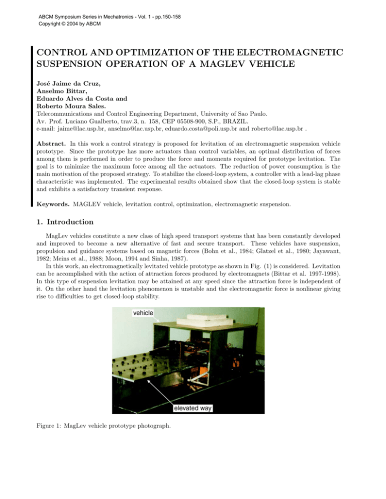
In this work, an electromagnetically levitated vehicle prototype as shown in Fig. (1) is considered. Levitation
can be accomplished with the action of attraction forces produced by electromagnets (Bittar et al. 1997-1998).
In this type of suspension levitation may be attained at any speed since the attraction force is independent of
it. On the other hand the levitation phenomenon is unstable and the electromagnetic force is nonlinear giving
rise to difficulties to get closed-loop stability.
Figure 1: MagLev vehicle prototype photograph.
Four electromagnets are located at the corners of the prototype to produce the attraction forces and four
inductive sensors are used to measure the gaps of the electromagnets. The prototype scheme is presented in
Fig. (2).
60 c
m
z
η
3
center
of mass
43 cm
φ
2
y
x
θ
4
1
70
20.5
cm
cm
1, 2, 3, 4: electromagnets
Figure 2: Vehicle scheme.
The prototype will have independent levitation, guidance and propulsion systems but only levitation is
considered in this paper. The system is modelled assuming rigid body dynamics. Levitation is achieved by
controlling its three degrees of freedom, namely, heave z(t), roll φ(t) and pitch θ(t). Since in normal operation
these variables are small, the system equations can be linearized around the reference equilibrium point (zref ,
φref = 0, θref = 0). Three decoupled SISO systems then result for which the vertical force Fz (t) and the
moments Mx (t) and My (t) are the control variables.
At least four electromagnets are required for vehicle levitation since the electromagnetic forces are attractive
and both positive as well as negative moments Mx (t) and My (t) may be necessary to control roll and pitch
angles. An optimization problem is defined to evaluate the forces to be produced by the four electromagnets
in order to get the three control variables above. The goal is to minimize the maximum force among all the
actuators.
Four inductive sensors are used to measure the gaps of the electromagnets. This choice improves the quality
of the measurement system since just three of them would be sufficient. Such redundancy also increases system
reliability to sensor faults. The controller inputs (z(t), φ(t) and θ(t) errors) are evaluated using the measured
gaps (zj (t), j = 1, . . . , 4).
In practice the levitation of electromagnetic suspension vehicles has a large number of actuators. The
levitation control based on three SISO systems together with an optimal operation of the actuators may be
used to improve system reliability by redistributing the forces in case of actuator faults. It is also expected that
the proposed control scheme reduces the energy consumption required for levitation since power loss in each
electromagnet is roughly proportional to its electromagnetic force.
Tab. (1) contains some prototype data.
Table 1. Prototype data.
Length
Width
Height
Vehicle mass
70 cm
60 cm
43 cm
97.6 kg
Nominal air gap
Levitation power
Supply voltage
Steady state current in each coil
0.005 m
377 W
55 VDC
1.71 A
The paper is organized as follows. Section 2 discusses briefly the prototype actuators. Section 3 contains
the system model. Section 4 describes the optimal operation of the actuators. In section 5 the measurement
processing to estimate the three controller inputs from the four measured gaps is presented. A brief description
of the SISO controller for each degree of freedom is made in section 6. Section 7 contains the experimental
results. The main conclusions are then summarized in section 8.
2. Prototype Actuators
a
Guideway
F
4
F
2
a
z
F
4
a
Inductive
gap
sensor
i
N
a
4a
a
2a
a
c
Figure 3: Electromagnet.
Each levitation electromagnet has an “E” shape as shown in Fig. (3) and its attraction force is given by
F(t) = kf
i(t)
z(t)
2
(1)
where i(t) is the current, z(t) is the air gap and kf is a constant.
For a given air gap z(t) the electromagnetic force is thus proportional to the current squared. Hence the
levitation power loss in a given actuator can be minimized by minimizing its electromagnetic force.
The choice of the steady state gap is directly related to the conflicting requirements of energy consumption
and performance of the levitation control system. From the point of view of energy consumption, it would
be interesting to set the gap as small as possible since the current required for vehicle levitation would be
proportionally small. On the other hand the coil inductance would also be high difficulting a fast control action.
Furthermore small gaps may give rise to magnetic saturation.
3. System Modelling
z
F3
F2
Center
of mass
F4
φ
L
θ
B
x
Figure 4: Scheme of forces.
y
F1
B
L
Fig. (4) shows a scheme of forces for prototype levitation. A dynamical model for this system can be easily
written if we assume rigid body dynamics and the occurrence of small displacements around the equilibrium
point represented by a given zref , φref = 0 and θref = 0:
Mz̈(t) = Mg − Fz (t)
(2)
Ixx φ̈(t) = Mx (t)
(3)
Iyy θ̈(t) = My (t)
(4)
where Fz (t) is the resultant vertical force, Mx (t) and My (t) are the components of the moment along the x and
y axes, respectively, Ixx and Iyy are the corresponding moments of inertia, M is the vehicle mass and g is the
local gravity acceleration. In the present case, M = 97.6kg, Ixx = 5.9kgm2 and Iyy = 7.9kgm2 .
The dynamical model has thus the form of a decoupled system of linear equations. Heave, roll and pitch
dynamics are given respectively by equations (2), (3) and (4).
As shown in the closed-loop system block diagram of Fig. (5), the gap z(t) has to be regulated around a
given reference value zref whereas both roll φ(t) and pitch θ(t) angles have to be regulated around zero.
z ref
φref = 0
+-
Fz (t)
Heave
Controller
+-
Mx (t)
Roll
Controller
θref = 0
+-
Command z(t)
of Actuators
+
Vehicle
φ (t)
+
M y (t) Measurement θ (t)
Pitch
Processing
Controller
Figure 5: Closed-loop system block diagram.
The system dynamical model has thus three inputs (Fz (t), Mx (t) and My (t)) and three outputs (z(t),
φ(t) and θ(t)). On the other hand the prototype has four inputs (ij (t), j = 1, . . . , 4) and four outputs (zj (t),
j = 1, . . . , 4).
To fully compatibilize the variables of the problem, two blocks, namely, command of actuators and measurement processing, are defined and included in the control loop. As indicated in Fig. (6), the inputs to the
first block are the control variables generated by heave, roll and pitch controllers; its outputs are the currents
to be applied to the electromagnets. The measurement processing block must compute the values of heave as
well as of both roll and pitch angles based on the four gap measurements.
A detailed exposition of the contents of these blocks is done in the following sections.
Fz (t)
Command
Mx (t)
of
M y (t) Actuators
Figure 6: Detail of the system diagram.
i 1 (t)
z 1 (t)
i 2 (t)
z2 (t)
z(t)
Measurement
Vehicle
i 3 (t)
z 3 (t)
i 4 (t)
z 4 (t)
Processing
φ (t)
θ (t)
4. Optimal Operation of Actuators
The purpose of the command of actuators is, at each time t, to compute the four electromagnetic forces
(F1 (t), F2 (t), F3 (t), F4 (t)) in order to produce the three control variables (Fz (t), Mx (t), My (t)) required by
the SISO controllers. The indetermination present in this problem can be removed by defining an optimization
problem.
Let Fu (t) be an upper bound on the electromagnets forces:
Fu (t) ≥ F1 (t), F2 (t), F3 (t), F4 (t) .
(5)
The goal is to minimize Fu (t) subject to the constraints that follow. For sufficiently small roll φ(t) and pitch
θ(t) angles, the following approximations hold
Fz (t) = F1 (t) + F2 (t) + F3 (t) + F4 (t) ,
(6)
Mx (t) = (F1 (t) + F2 (t) − F3 (t) − F4 (t))B ,
(7)
My (t) = (−F1 (t) + F2 (t) + F3 (t) − F4 (t))L .
(8)
where B and L are the lengths shown in Fig. (4).
Since the electromagnets produce only attraction forces, the following additional constraints must be included
F1 (t), F2 (t), F3 (t), F4 (t) ≥ 0 .
(9)
The solution of the Linear Programming Problem (LPP) of minimizing Fu (t) subject to the set of constraints
of equations (5)-(9) can be obtained analytically. From equations (6)-(8) it follows that
F1 (t)
F2 (t)
=
=
a1 (t) − F4 (t) ,
a2 (t) + F4 (t) ,
(10)
(11)
F3 (t)
=
a3 (t) − F4 (t) ,
(12)
where
∆
a1 (t) =
∆
a2 (t) =
∆
a3 (t) =
1
My (t)
Fz (t) −
,
2
L
1 Mx (t) My (t)
+
,
2
B
L
1
Mx (t)
Fz (t) −
.
2
B
(13)
(14)
(15)
Using equations (10)-(12) and defining
∆
b1 = max { 0 , −a2 } ≥ 0 ,
∆
b2 = min { a1 , a3 } ≥ 0 ,
(16)
(17)
the constraints (9) can be rewritten as
F4 (t)
≥
b1 ,
(18)
F4 (t)
≤
b2 .
(19)
Similarly, defining
∆
b3 = max { a1 , a3 } ≥ 0 ,
∆
b4 = min { 0 , −a2 } ≤ 0 ,
(20)
(21)
inequalities (5) can be rewritten as
Fu (t)
Fu (t)
≥ −F4 (t) + b3 ,
≥
F4 (t) − b4 .
(22)
(23)
Fig. (7) illustrates the constraints (18), (19), (22) and (23) on Fu (t) and F4 (t).
Fu (t)
b3
Fu (t) > F4 (t) - b4
Fu (t) > - F4 (t) + b3
b1
b2
F4 (t) > b1
F4 (t)
F4 (t) < b2
Figure 7: Constraints on Fu (t) and F4 (t).
Since the goal is to minimize Fu (t), a straightforward analysis of this figure leads to the optimal solution
F∗4 (t):
b3 + b4
< b1 ⇒ F∗4 (t) = b1 ,
2
(24)
b1 ≤
b3 + b4
b3 + b4
≤ b2 ⇒ F∗4 (t) =
,
2
2
(25)
b2 <
b3 + b4
⇒ F∗4 (t) = b2 .
2
(26)
Substituting F∗4 (t) into equations (10)-(12) the problem is solved.
A straightforward analysis shows that b1 ≤ b2 . The optimization problem has thus always a solution.
5. Measurement Processing
The purpose of the measurement processing described in the following is to evaluate the gap z(t) and the
angles φ(t) and θ(t), using the measurements of the four gaps taken by the sensors.
The heave displacement z(t) is given by the mean value of the four measured gaps:
z(t) =
1
(z1 (t) + z2 (t) + z3 (t) + z4 (t)).
4
(27)
Fig. (8) shows a sketch of the section of the vehicle contained in the y − z plane ( see Fig. (4) ).
z
z φ2
z φ1
φ
y
b
Figure 8: Section of the vehicle in the y − z plane with roll angle shown.
Assuming small deviations of the gaps from the reference value and defining
zφ1 (t) =
z1 (t) + z2 (t)
,
2
(28)
zφ2 (t) =
z3 (t) + z4 (t)
,
2
(29)
the angle φ(t) can be approximated by
φ(t) ∼
=
zφ2 (t) − zφ1 (t)
,
b
(30)
where b is the distance between the sensors measured along axis y.
In the same way, after defining
zθ1 (t) =
z2 (t) + z3 (t)
,
2
(31)
zθ2 (t) =
z1 (t) + z4 (t)
,
2
(32)
an approximation for θ(t) can be written as
θ(t) ∼
=
zθ2 (t) − zθ1 (t)
,
l
(33)
where l is the distance between the sensors measured along axis x.
Thus, the gap z(t) and both angles φ(t) and θ(t) can be estimated using equations (27), (30) and (33).
6. Controllers
Heave, pitch and roll controllers have been obtained using the H2 /H∞ theory (Doyle et al. 1989). Their
transfer functions are given by
Gc (s) =
Kc (s + 0.8)(s + 60.0)(s + 62.6)(s + 100.0)
,
s(s + 57.5)(s + 71.5)(s + 301.7 ± 299.2j)
(34)
where the gain Kc has been tuned for each controller. The controllers have been discretized using the well-known
Tustin approximation and implemented in a microcomputer with a sample rate of 3.5 kHz.
It is worth to mention some important features of Gc (s):
• it has a lead-lag phase characteristic;
• occurrence of phase lead in low frequencies which is essential to produce closed-loop stability since the
open-loop models have two poles at the origin;
• presence of high-frequency poles to reject sensor noise;
• presence of an integrator to obtain null steady-state error for step inputs at the reference (as in the case
of levitation starting) and step disturbances at the plant input (as in the case of load disturbances).
System stabilization for gaps significantly different from the nominal one is difficult: large gaps require
excessive electrical power whereas small gaps give rise to high electromagnet inductances difficulting fast control
actions.
7. Experimental Results
The closed-loop response for a reference gap of 5 mm has been considered. A step disturbance has been
applied to the plant by suddenly laying a mass of 3kg on the vehicle.
Fig. (9) shows the heave, roll and pitch errors. It can be seen that the closed-loop system is stable as
expected. The disturbance has been completely rejected in steady-state.
Fig. (10) shows the four gaps as functions of time. The presence of coupling can be clearly observed.
Furthermore, all gaps oscillate in phase indicating that the heave resonant frequency of the vehicle is predominant
over both roll and pitch ones being less damped than them.
Both figures show that the transient response exhibits a settling time of about 0.5 sec.
−3
Z error (mm)
2
1
0
−1
−2
φ error (rad)
2
0
−3
x 10
0.5
1
1.5
2
t (sec)
2.5
3
3.5
4
0
−3
x 10
0.5
1
1.5
2
t (sec)
2.5
3
3.5
4
0
0.5
1
1.5
2
t (sec)
2.5
3
3.5
4
1
0
−1
−2
2
θ error (rad)
x 10
1
0
−1
−2
Figure 9: z, φ and θ error signals as functions of time.
6
6
Z2 (mm)
7
Z1 (mm)
7
5
5
4
3
4
0
1
2
t (sec)
3
4
3
6
6
5
2
t (sec)
3
4
0
1
2
t (sec)
3
4
5
4
3
1
Z4 (mm)
7
Z3 (mm)
7
0
4
0
1
2
t (sec)
3
4
3
Figure 10: Gaps z1 to z4 shown as functions of time.
8. Conclusions
A control approach to the levitation of an electromagnetic suspension vehicle prototype based on the optimal
operation of the actuators has been proposed in this paper. The main motivation has been to reduce energy
consumption. The control scheme can also be employed to improve system reliability in case of actuators faults.
Experimental results have been shown to illustrate the application of the control approach to a vehicle
prototype.
The same approach could be employed in different systems whenever the number of actuators is greater
than the the number of control variables. A typical application is the dynamic positioning of offshore platforms
using thrusters.
9. Acknowledgements
This work was supported by FAPESP (Sao Paulo State Research Council) under grant 95/6968-7. The first
author is indebted to CNPq for its support under grants No. 304071/85-4(RN) and 66.2015/1998-3.
10. References
Bittar, A. and Sales, R. M., 1997, “H2 and H∞ control applied to an electromagnetically levitated vehicle”,
IEEE International Conference on Control Applications, October 5-7, Connecticut, USA.
Bittar, A. and Sales, R. M., 1997, “Control results for an electromagnetically levitated vehicle prototype”,
European Control Conference, ECC, July, Belgium.
Bittar, A., Cruz, J. J. and Sales, R. M., 1998, “A New Approach to the Levitation Control of an Electromagnetic
Suspension Vehicle”, IEEE International Conference on Control Applications, CCA, Italy.
Bittar, A. and Sales, R. M., 1998, “H2 and H∞ control for MagLev Vehicles”, IEEE Control Systems Magazine,
Vol. 18, No. 4, pp.18-25.
Bohn, G. and Steinmetz, G., 1984, “The electromagnetic levitation and guidance technology of the TRANSRAPID test facility emsland”, IEEE Transactions on Magnetics, Vol. MAG-20, No . 5, pp. 1666-1671.
Doyle, J. C., Glover, K., Khargonekar, P. P. and Francis, B. A., 1989, State-Space Solutions to Standard H2
and H∞ Control Problems, “IEEE Transactions on Automatic Control”, Vol. AC-34, pp. 831-847.
Glatzel, K., Khurdok G. and Rogg, D., 1980, “The development of the magnetically suspended transportation
system in the federal republic of germany”, IEEE Transactions on Vehicular Technology, Vol. VT-29, No .
1, pp. 3-16.
Jayawant, B. V., 1982, “Electromagnetic suspension and levitation”, Proceedings of the IEE, Vol. 129, Pt. A,
No . 8, pp. 549-581.
Meins, J., Miller, L. and Mayer, W. J., 1988, “The high speed MAGLEV transportation system TRANSRAPID”,
IEEE Transactions on Magnetics, Vol. MAG-24, No . 2, pp. 808-811.
Moon, F. C., 1994, “Superconducting Levitation: Applications to Bearings and Magnetic Transportation”, John
Wiley and Sons.
Sinha, P. K., 1987, “Electromagnetic suspension: dynamics and control”, Peter Peregrinus Ltd, London.


