Voltmeter design
advertisement
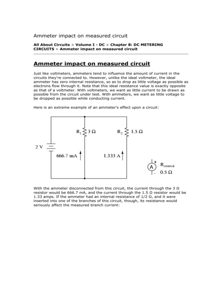
Ammeter impact on measured circuit All About Circuits > Volume I - DC > Chapter 8: DC METERING CIRCUITS > Ammeter impact on measured circuit Ammeter impact on measured circuit Just like voltmeters, ammeters tend to influence the amount of current in the circuits they're connected to. However, unlike the ideal voltmeter, the ideal ammeter has zero internal resistance, so as to drop as little voltage as possible as electrons flow through it. Note that this ideal resistance value is exactly opposite as that of a voltmeter. With voltmeters, we want as little current to be drawn as possible from the circuit under test. With ammeters, we want as little voltage to be dropped as possible while conducting current. Here is an extreme example of an ammeter's effect upon a circuit: With the ammeter disconnected from this circuit, the current through the 3 Ω resistor would be 666.7 mA, and the current through the 1.5 Ω resistor would be 1.33 amps. If the ammeter had an internal resistance of 1/2 Ω, and it were inserted into one of the branches of this circuit, though, its resistance would seriously affect the measured branch current: Having effectively increased the left branch resistance from 3 Ω to 3.5 Ω, the ammeter will read 571.43 mA instead of 666.7 mA. Placing the same ammeter in the right branch would affect the current to an even greater extent: Now the right branch current is 1 amp instead of 1.333 amps, due to the increase in resistance created by the addition of the ammeter into the current path. When using standard ammeters that connect in series with the circuit being measured, it might not be practical or possible to redesign the meter for a lower input (lead-to-lead) resistance. However, if we were selecting a value of shunt resistor to place in the circuit for a current measurement based on voltage drop, and we had our choice of a wide range of resistances, it would be best to choose the lowest practical resistance for the application. Any more resistance than necessary and the shunt may impact the circuit adversely by adding excessive resistance in the current path. One ingenious way to reduce the impact that a current-measuring device has on a circuit is to use the circuit wire as part of the ammeter movement itself. All current-carrying wires produce a magnetic field, the strength of which is in direct proportion to the strength of the current. By building an instrument that measures the strength of that magnetic field, a no-contact ammeter can be produced. Such a meter is able to measure the current through a conductor without even having to make physical contact with the circuit, much less break continuity or insert additional resistance. Ammeters of this design are made, and are called "clamp-on" meters because they have "jaws" which can be opened and then secured around a circuit wire. Clamp-on ammeters make for quick and safe current measurements, especially on high-power industrial circuits. Because the circuit under test has had no additional resistance inserted into it by a clamp-on meter, there is no error induced in taking a current measurement. The actual movement mechanism of a clamp-on ammeter is much the same as for an iron-vane instrument, except that there is no internal wire coil to generate the magnetic field. More modern designs of clamp-on ammeters utilize a small magnetic field detector device called a Hall-effect sensor to accurately determine field strength. Some clamp-on meters contain electronic amplifier circuitry to generate a small voltage proportional to the current in the wire between the jaws, that small voltage connected to a voltmeter for convenient readout by a technician. Thus, a clamp-on unit can be an accessory device to a voltmeter, for current measurement. A less accurate type of magnetic-field-sensing ammeter than the clamp-on style is shown in the following photograph: The operating principle for this ammeter is identical to the clamp-on style of meter: the circular magnetic field surrounding a current-carrying conductor deflects the meter's needle, producing an indication on the scale. Note how there are two current scales on this particular meter: +/- 75 amps and +/- 400 amps. These two measurement scales correspond to the two sets of notches on the back of the meter. Depending on which set of notches the current-carrying conductor is laid in, a given strength of magnetic field will have a different amount of effect on the needle. In effect, the two different positions of the conductor relative to the movement act as two different range resistors in a direct-connection style of ammeter. • • • • REVIEW: An ideal ammeter has zero resistance. A "clamp-on" ammeter measures current through a wire by measuring the strength of the magnetic field around it rather than by becoming part of the circuit, making it an ideal ammeter. Clamp-on meters make for quick and safe current measurements, because there is no conductive contact between the meter and the circuit kilde: http://www.allaboutcircuits.com/vol_1/chpt_8/5.html den 5-9-05

