Guide for testing and verification of low voltage installations
advertisement
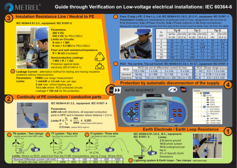
Guide through Verification on Low-voltage electrical installations: IEC 60364-6 3 Insulation Resistance Line / Neutral to PE Fuse: Z loop L-PE / Z line L-L, L-N IEC 60364-6 61.3.6.3., 61.3.11., equipment: IEC 61557- 3 Parameters / Limits are characteristics of particular built-in Fuse, designed for trip-out time of: 0.1s (Explosive), 0.2s (3Phase Circuits), 0.4s (1Phase systems) or 5s (fixed connections). Measured values of Impedances from the end of the circuit must be lower than Zs from the table. IEC 60364-6 61.3.3., equipment: IEC 61557-2 Parameters: 500 V DC 250 V DC for PELV/SELV Limits on Circuits: R min > 1 MΩ R min > 0.5 MΩ for PELV/SELV In (A) 2 4 6 10 16 20 Floor and wall resistance/impedance R > 50 kΩ (insulated) Semiconductive coatings 1 MΩ < R > 1 GΩ Protection against static electricity (EN 61340-5-1) Tip G In Zs=(Ω) (A) (0,4 s) 16 13,7 32 6,8 47 4,6 82 2,6 110 2,0 147 1,4 More Parameters/Limits could be found in Metrel Handbooks and inside Eurotest/Smartec testers. Leakage Current - alternative method for testing and tracing insulation problems without disconnection Parameters:TRMS Low range measurement Limits: 1 mA/kW or 3.5 mA max. per app. 5 mA max. where heating app. 1/3 x Idn where RCD protected circuits. Leakage < 100 mA for fire protection. 2 Tip B Tip C Ia=5x Zs=(Ω) Ia=10x Zs=(Ω) In (A) (0,2 s) In (A) (0,2 s) 10 22 20 11 20 11 40 5,5 30 7,3 60 3,65 50 4,4 100 2,2 80 2,8 160 1,4 100 2,2 200 1,1 RCD: Trip out time, Trip out Current IEC 60364-6 61.3.6.1., 61.3.7., equipment: IEC 61557- 6 RCD trip out at differential current Id (ms) RCD Slope range (from-to) RCD AC 1/2 x I∆N 1 x I∆N 2 x I∆N 5 x I∆N 0.5 ÷ 1.0 x I∆N General No trip t∆ < 300 t∆ < 150 t∆ < 40 0.35 ÷ 1.4 x I∆N A Selective No trip 130 x t∆ < 500 60 x t∆ < 200 50 x t∆ < 150 0.5 ÷ 2.0 x I∆N B Protection by automatic disconnection of the supply AUTO SEQUENCE ® 4 Continuity of PE conductors / conductive parts IEC 60364-6 61.3.2., equipment: IEC 61557- 4 Parameters: ±200 mA both directions, all exposed conductive parts to MPE and in between where distance < 2.5 m. U 50V R≤ c ≤ ≤ 0,25Ω Limits: 200A I (where Fuse C20A built-in) pfc or 2 Ω max. (where RCD built-in) TN system - Two clamps - clamps arround main N/PE cable L1 TT system - Two wire - test from the socket N to PE PE - test leads to rods in triangle L1 L2 L3 N L2 L3 N TN IT system - Three wire TT PE L1 L2 L3 N TT PE Limits: Where no RCD, select limit from the FUSE characteristics, test by Z loop. Where RCD: Nominal Differntial current I∆N (mA) 10 30 100 300 500 1000 R earth (Ω) max. (Uc<25 V) 2500 833 250 833 50 25 Earth Electrode / Earth Loop Resistance IEC 60364-6 61.3.6.2., B.3., equipment: IEC 61557- 5 Limits: 2 Ω above ground 10 Ω whole system 10 Ω underground per leg or 8% of Specific Earth Resistance Lightning system & Earth loops - Two clamps - test each loop 1 Reports and Certificates on Low-voltage electrical installations: IEC 60364-6

