electrostatic voltmeters
advertisement
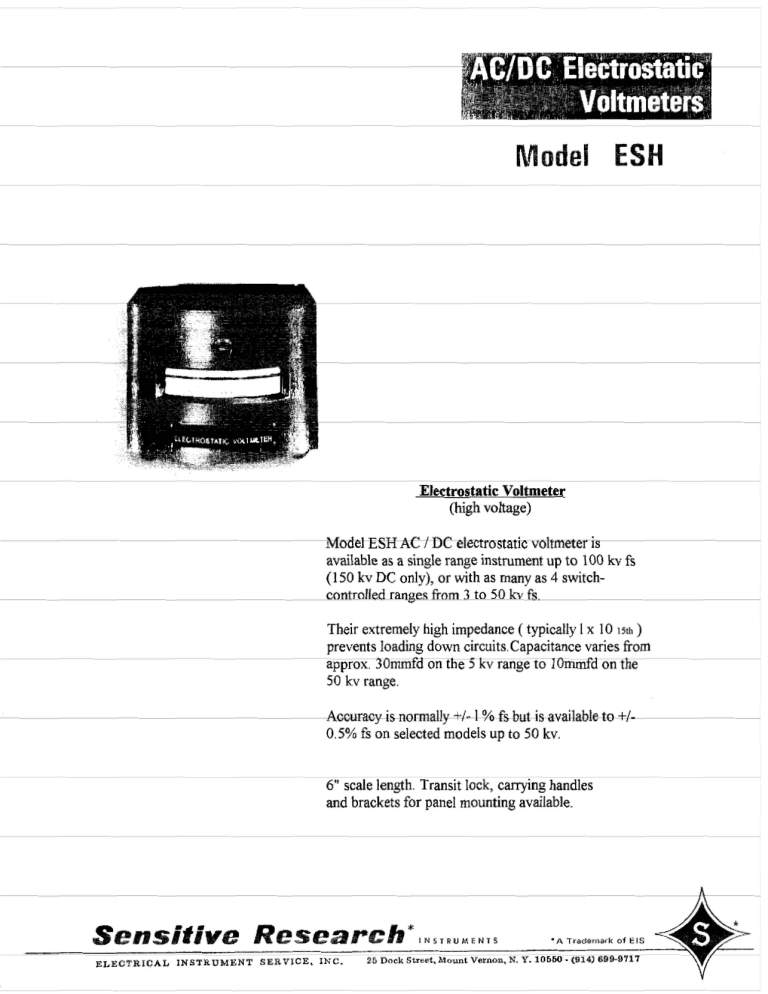
Electrostatic Voltmeter
(high voltage)
Model ESH AC / DC dectrostatie volt meter is
available as a sin& range instrument up to 100 kv fs
(150 kv DC only), or with as many as 4 switchcontrolled ranges from 3 to 50 kv fs.
Their extremely high impedance ( typically 1 x 10 15th )
prevents loading down circuits.Capacitancevaries from
approx. 3 Ommfd an the 5 kv range to l O d d on the
50 ikv range.
.Accuracy is normally +/.I-1 % fs but is available to +/0.5% fs on selected models up to 50 h.
6" scale length. Transit lock, canying handles
and brackets for panel mounting avaiIabfe.
T R I C A L I N S T R U M E N T SERVICE. INC.
25 Dock Street, Mount V-n,
N. Y . 106W -(a14) 6989717
ELECTROSTATIC VOLTMETERS
5 % .c,u,,y
.,lo,
SPECIFICATIONS
Double Pivoted Movement
AC/DC PORTABLE - HORIZONTAL USE
SINGLE RANGE
ACCURACY II 1 % or .5%
SCALE LENGTH I 6 inches
SCALE DIVISIONS I up to 100 as r e q u i r e d
PERIOD I1 3 - 5 seconds
TYPE I Electrostatic
PIVOTS 1 Diamond Pivoted
I
IEWELS I Sapphire S p r i n g Moun!ed
CAPACITY S e e below
SHIELDING E l ~ ~ + r o ~ + ~ + i c
I
RANGE CHANGING I Multirange, switch controlled
CASE 1 Cast Aluminum
SIZE I Tabfe on r i g h t
INST. WEIGHT
I
able
Moder
ESH-I
ESH-2
ESH-3
ESH-4
Ranga-
Code
(KVI
Word
7.5
10
15
20
ESHOLM
ESHILT
ESHAIM
ESHUNS
ESHULK
ESHORE
ESHPOT
ESHIQH
ESHPEC
ESHHlY
ESHOOP
ESHCXL
ESH I EM
Lowest
Case
Style
Reading
r- FOR USE ON DC ONLY
t-ACCURACY DC 2%
on riqht
HIGH VOLTAGE ELECTROSTATIC DESIGN
MULTIRANGE VOLTMETERS
FOR A.C. AND D.C.
By using a uniquely designed internal high voltage
switch, multiranges o f voltages from 3000 full scale volts
up to 50,000 volts are obtained. This system has a distinct advantage because the capacity of the instrumenl
decreases as +he ranges increase. Briefly explained, the
switch operating in successive "clickt' positions, moves the
stcltor electrode away from the rotor in predetermined positions. The voltmeter i s not limited to AC but can be used
over all its ranges on DC. The capacity of i t s lowest range
(3000 volts) i s approxirnotely 11 mmfd, and is about 10
mmfd a t 50 to 100 kilovolts.
The insulation resistance of these instruments is very
on the 75 K.V. and I00 K.V. design it
high-for
instance
i s more
than 5 x 10';
ohms.
SWITCH CONTROLL€ D MLILTIRANGE VOLTMETERS
-
ESH -30
ESH-31
ESH-32
ESH - 33
Code
Range
-
Case Type
Lowest Reading
ESHAKE
5/10 KV
511 5
A
I000 v
1000
2000
2000
2000
3000
1000
1000
1000
2000
€SHEEP
ESHICK
ESHOTS
ESHAMP
ESHULE
ESHUL
ESHMIP
ESHMOT
ESHMUS
ESHMIX
ESHUTE
ESHMOO
ESHMEE
ESHMAY
ESHMAX
ESH DCH
ESHMl L
ESHALL
ESHALE
ESHAME
10115
10/20
A
A
A
A
A
A
A
A
A
B
A
A
A
B
B
A
A
A
B
B
NOTE: Atl Models except ESH - 9, 10,11, '12.12M. available a t 0.5% Accuracy
2dd0
1000
1000
1000
2000
7 000
600
600
600
4000
5000
ELECTROSTATIC VOLTMETERS
HOW TO ORDER A MODEI- ESH
NON-CATALOG INSTRUMENTS
INSERT "X" FOR 0.5%
ACCURACY OPTION.
INSERT "C" FOR HANDLES
OPTION OR "D" FOR
MOUNTING BRACKET OPTION
OR "T" FOR TRANSIT LOCK
OPTION.
ANY COMBINATION OF UP TO 4 RANGES C A N BE
SUPPLIED PROVIDING:
(A) RANGES ARE BETWEEN 3 AND 50 KV.
(B) RANGES ARE SPACED A T LEAST 5 KV APART.
(C) RATIO BETWEEN HIGHEST AND LOWEST RANGE
IS NOT GREATER THAN 10:l.
COST \!/ILL BE THE SAME PRICE AS AN INSTRUMENT
HAVING THE SAME NUMBER OF RANGES AND THE
SAME HIGHEST FULL SCALE RANGE. IF THE
SAME HIGHEST RANGE IS NOT LISTED, USE PRICE
FOR THE NEXT HIGHER RANGE.
I
INSERT MODEL.
EXAMPLE: ESH 7 DX = A 40 KIL.OVOLT INSTRUMENT
WITH MOUNTING BRACKET AND
0.5% ACCURACY.
Shipping
16" x 1 3 " x 9
23-1/2" x 13" x 14-1/2"
42-112" x 21-114" x 22"
52" x 27" x 26"
21 Ibs.
29 Ibs.
29 Ibs.
39 Ibs,
101 lbs. 217 lbs.
1451bs. 358 Ibs.
Outline
Dimensions
1
221
Case Style A
Case Style
B I C, D
Model VPA
Model Park
CHARACTERISTICS OF THE
ELECTROSTATIC VOLTMETER
Measures True Voltage Directly
Measures RMS Voltage of all Waveforms
The outstanding feature o f electrostatic voltmeters is that
they represent the only true method o f measuring voltage
directly. Conventional voltmcters universally measure voltage as a function of current. The electrostatic voltmcte~
operates directly f r o m the impressed voltage and draws
virtually n o current. Any current that does f l o w is incidental to the measurement afld is n o t the cause of the
deflection. The deflection i s directly proportional only t o
the rms value of the voltage appearing bc:wecn t h e plates.
Tlla clcctrostatic voltmeter measures rrns voltage whether
the voltagc is DC, sinusoidal AC, or pulsed. The pulse or
high-peaked type of voltage wave usually has an rrns value
which i s small compared to ;he peak value. This sometimes
misleads the user into thinking that the instrument i s not
On DC the instrument draws a momentary charging currcn:
which instantly drops KO a negligible value determined by
the insulation resis:ance of the instrument. The irlsr~lation
resistance is always several terohns and varies with t h e
type o f instrument. temperature, hi~rnidiryand other factors. However, under the worst conditions. charging current f r o m thfs cause is several hundred times smaller than
the current draw11 by any other type o f voltmeter. I n the
great majority o f steady DC circuits, the clcctrostatic voltlnctcr can bc considered a "zero current" device.
Olperates Over Wide Frequency Range
The frequency ranoe o f the electrostatic voltmeter i s atmost
unlimited. There are three factors which place rlie upper
frequency l i m i t o n the use of the instrument.
The first i s the effect of loading on the circuit being measured. The voltmeter as a circuit element is a very low loss
capacitor. Its capacitance lies between the limits of 225 pf
for the 120 volt instruments to about 10 pf for the
100 kilovolt type. I n the radio frequency range, the reactance of the instrument is a quantity t o be considered.
The sccond limitation i s that the instrument and its leads
behave as a resonant or partially resonant transmission line.
The leads and the capacitive termination formed by the
voltmeter movement may result i n a voltage distribution
along thr! line which i s not constant. Thus the instrument
may indicate a voltage which is not the same as that t o
which :he leads are connected.
The t h i r d limitation is the current-carrying capacity of the
instrument. For any given combination of voltage and frequency, such capacity will allow a current t o flow. This
current must not exceed 200 mA (forall models) or a permanent change in calibration may occur. This poses an
upper frequency l i m i t which is dependent o n the voltage
level used w i t h the instrument.
For example: a 30 kilovoll instrument {capacity abour 10 pf)
at 20 kilovolt, could be used up t o approximately 160 kHz.
functioning properly.
The instantaneous torque developer! by the electrostatic
voltmeter i s equal t o a constant (for a given deflection)
multiplied by the square of the instantaneous termilal
voltage. I f the instantaneous terminal voltage is steady DC,
then the average torque which produces the deflection is
the same as the i~istantaneoustorque and the instrument
reads DC voltage. \When alternating voltages are applied.
the instantaneous torque o f rhc elect:ostatic voltmeter is
proportional t o the square of the instantaneous terminal
voltage. This results i n the alternating voltage producing
surges of torque which arc mcclianically svcragcd by the
instrument movement.
The instrument movement can do an accurate averaging job
because i t has a mechanical time constant which is very
long, compared t o the period of the alternating voltage
being measured. Consequently. the instrument responds 70
the theoretical concept o f root mean square voltage, rcgardless of wave shape.
Since the electrostatic voltmeter as a circuit element is a
high quality capacitor, the power taken by the instrument
is negligible.
Multirange Instruments
Sensitivity of an elettrostatic voltmeter depends upon :he
spacing of the electrodes and can therefore be altered bv
varying the electrode spacing. The SENSITIVE RESEARCH
Model ESH High Voltage Electrostatic Voltmeter uses this
principle in a very refined mechanism f o r positioning the
stationary electrode i n as many as four positions t o obtain
an equivatent number of voltage measurements w i t h one
instrument. The ranaes avai!able are shown o n page 6. The
Model ESH also has the advantage of the voltmeter capacity
decreasing as the voltage range increases.
The Model ESD electrostatic voltmeters obtain their multiranges by different means. It is not convenient t o vary the
spacing of the electrodes i n the more sensi:ive instruments
and so capacity type voltage multipliers are used. From
the circuit shown i n Figure I , the condensers f o r m a voltage
divider for AC components which provide fixed accurate
multiplying factors. The dotted resistances shown represent leakage resistances of the individual condensers used
i n the divider when DC is applied.
Due to normal
High voltage rneasi~rbrnentsor? high reactaljce transformers,
such as those used for catllode ray tube supplies atid low
current, high voltagi. supplies for breakdown testing, are
examplcs requiring high vcltage measurements at low current drain.
It should also be noted that this is a completely reactive
current and there is no power consumption even a t low
leve!s. This is i~sua!lya theoretical advantage, however,
rather than o f practical importance.
The inclusion of an electrostatic voltmeter for AC rneasurements at power frequencies may in many cases eliminate the ncccssit~of dcctronic circuitry with the attendant
difficulties of tube replacements, recalibrations, etc.
As an Extremely High Resistance DC Meter:
When used as a DC voltmeter, the electrostatic voltmeter has
no equal in having high input resistance a t high voltage.
The electrometer tube voltmeter for measuring a few volts
has a compa~.ableinput resistance, but when the range of
100 volts and up is reached, the electrostatic ins~rumenti s
i n a class by itself.
Fiqure 1
ma~iufacturingtolerances, t h ~ sleakage resistance can only be
held within a range above some given high value, but not
t o a definite value of resistance. The DC path is through
the leakage resistances. with the voltage apprarrng across
the movement being proportional. Since the leakage resis.
:antes are of undetermined values. the voltages appearing
across them are unreliable. For this reasor. multirange
Model ESD instrurntln:~ should be used for DC readings
only on the lowest range.
Special Uses for the Electrostatic Voltmeter:
As a High Impedance AC Voltmeter:
At commercial power frequencies, t h e electrostatic voltmeter provides a very high impedance instrument for man\,
Types of reasurcment.
For instance, :he Model ESH
30 kilovolt instrument a t 60 hertz has an input irnpeda~lce
of about 266 megohms. due to its capaci:ance, and draws a
current of only 120 microamperes. I t compares favorab!y
with any type of electronic instrument i n impedance, and is
much superior in long term stability.
At lower voltages such as 1000 vol~s, 60 hertz, the
Model ESD instrument with a capacitance of about 55 pf
draws a current of 20.5 microamperes. This represenls an
equivalent input impedance of 48.5 megohms.
An electrostatic voltmeter on DC draws only a momentary
charging current due to its capacitance and draws a very
low current thereafter. The value o f this current i s very
small. For instance, a 10.000 volt instrument has a leakage
resistance of at leas: 3 x 10'' ohms. After :he initial
charging current, such an instrument draws a current of
only 3 x 16" amperes, a cornpletel~negligible value.
This low curren? is extremely useful for many applications
such as Geiger counters, condenser microphones, ionization
chambers, etc. These devices employ a polarizino vollaye
from a very limited current source. I t is difficult t o measure these voltages with ordinary instl.uments because of
the current drain error. L4'irh the electrostatic voltmeter,
true readings are easily obtained. In fact, the current drain
is so low that i t can be neglected entirely and the meter
left connected for m ~ n i t o r i n gduring any operation.
"Atomic" betteries using a radioactiile source for providing
power in place of chemical action can be readily checked
with an electroststic voltmeter. Any oiher type instrument
will give incorrect low readings because of the limited current capebilities of this type of battery.
Any requirement for measuring voltage i n :he DC ranges,
from 30 :o 40 volts up to 100 kilovolts, in which very
limited power is available for operation of e n i ~ s t r u n e n t ,
becomes the natural field of measurement using the electro.
static voltmetcr.
CHARACTERISTICS OF THE
ELECTROSTATIC VOlThl ETER
(Corltinufd)
Other Uses
A t all times all electrostztic instrunent reads The r n l j va!ue
of the impressed voltage. This f a c t makes :hc instrumcnt
very i ~ s e f r ~
asl an AC-DC transfer standard, p a r t i c ~ ! a r l vin
the high voltage ranges where i t s low power cunsuml~tion
malccs i t an ~ttractivetransfer devicc. The praciicki y infin:t? impedance o f the i~~strcr~nent
makes i t a very s~ic:esjfuI
tool for tne ir-vestigation
electl-ostatic fields. 1;s st! in
the printing, textile and paper i n d ~ s ~ r i ci ss widesf?re;d. In
3 place vvhere quantities of a ? y ~ n s c ~ l a t ~matcr~al
rg
are
r-nuved, tr-oublesorne static ~1x1-ges
build u p . This Is partic.
ularly true where long c o n t i n u o ~ ~sheets
s
are handled.
Sratic tields cause stickinc, misfeeding, sparking ;rid other
difiiculties.
With an appropriate probe or collector, the electrostatic
instrumcnt will provide rncax~rcmcntof wide ficid: with
a n accuracy limited primsrily by the sensing devicp rather
t h a n rhe instrument.
The mcasclrelnent a n d plotting of
such fields is the first step in being able to eliminate them
to r h e r x t e n t r c q ~ i r e df a * satisfsctory performance of the
equiprner?t.
Tk~egeneral princip.e tc be obsel-ved in setting u p such a
messuretncnt system i s to provide a ~vellinsulated conductor from the ficid t o a "field-free" pcsit;on where it i s connected :o the high Yde of the electrostatic vc,ltmeter.
Ur~derr h ~ s econditions, the voltmeter reading will then be
directly propol-tional to the f i ~ i dintel-cepted by the cunductar. If such measurements have t o bc made a t a distance, shielded cable call be used to eliminate pickup on
tile leads. Howevei-, t h e cable mLst be uf exceptionally
high insulation value or i t will provide an attenuation of
ri.ading too great t o tolerate.
Scale Ranges
The ESD instruments u p t o 1,000 iin'ts have a I - [ e a r l y square
law s c a l e giving very satisfactory readings dowr~t o e b o ~ t
113 oi the full scale voltage with lowest calibrated p 5 n t a t
115 of fuli scale. Instruments above 1,000volts have scales
which terrd t o close dcwn a t ths u p p e r end.
The Model ESH has neither a true square law or liqear
I t s ac?u;l configuration is based on the full scale
range nf the instrument, and tho combir3ation of ranges
with wl.ict7 i t i s ~ncluded. I t s lowest cal~bratedpoint is
about 115 fu I scale,
scale.
MODEL ESD SCALE, FULL SIZE
MULTIRANGE MODEL ESH SCALE, FUL
Figure
2

