Non-contact surface charge/voltage measurements
advertisement
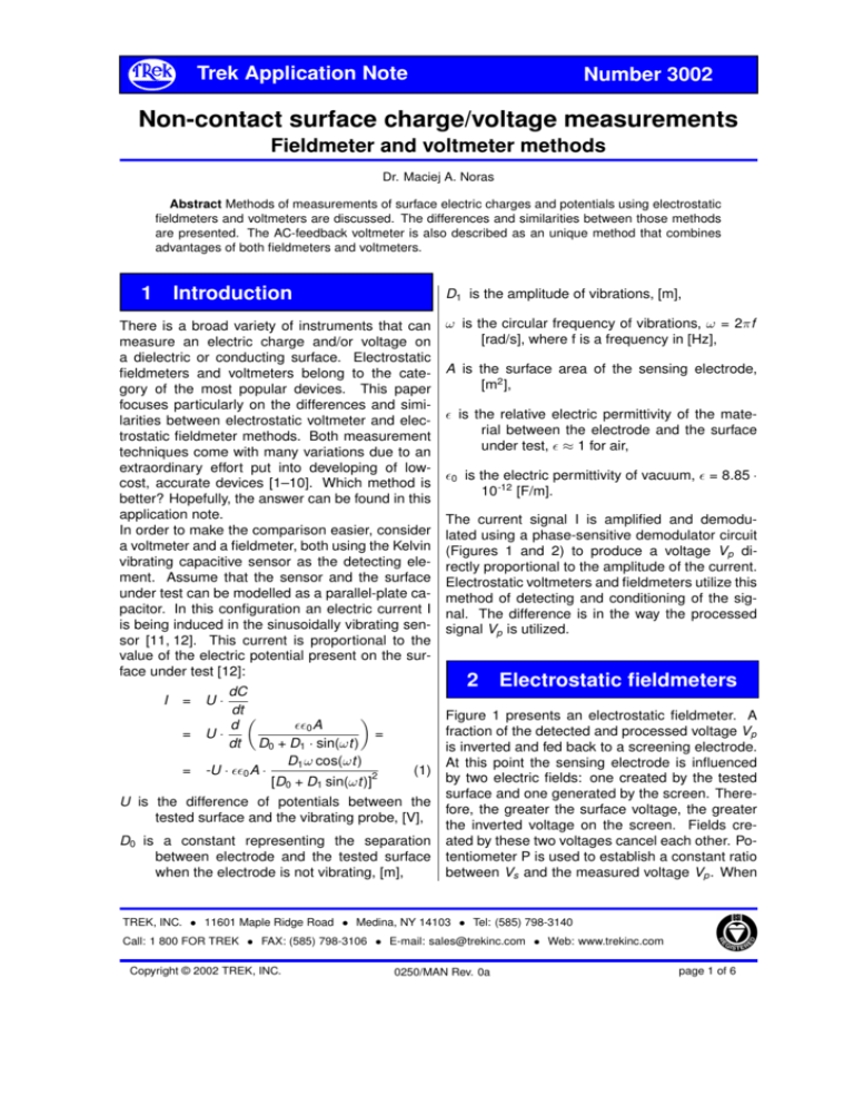
Trek Application Note Number 3002 Non-contact surface charge/voltage measurements Fieldmeter and voltmeter methods Dr. Maciej A. Noras Abstract Methods of measurements of surface electric charges and potentials using electrostatic fieldmeters and voltmeters are discussed. The differences and similarities between those methods are presented. The AC-feedback voltmeter is also described as an unique method that combines advantages of both fieldmeters and voltmeters. 1 Introduction D1 is the amplitude of vibrations, [m], There is a broad variety of instruments that can measure an electric charge and/or voltage on a dielectric or conducting surface. Electrostatic fieldmeters and voltmeters belong to the category of the most popular devices. This paper focuses particularly on the differences and similarities between electrostatic voltmeter and electrostatic fieldmeter methods. Both measurement techniques come with many variations due to an extraordinary effort put into developing of lowcost, accurate devices [1–10]. Which method is better? Hopefully, the answer can be found in this application note. In order to make the comparison easier, consider a voltmeter and a fieldmeter, both using the Kelvin vibrating capacitive sensor as the detecting element. Assume that the sensor and the surface under test can be modelled as a parallel-plate capacitor. In this configuration an electric current I is being induced in the sinusoidally vibrating sensor [11, 12]. This current is proportional to the value of the electric potential present on the surface under test [12]: I dC = U· dt 0 A d = U· = dt D0 + D1 · sin(ωt) D1 ω cos(ωt) = -U · 0 A · [D0 + D1 sin(ωt)]2 (1) U is the difference of potentials between the tested surface and the vibrating probe, [V], D0 is a constant representing the separation between electrode and the tested surface when the electrode is not vibrating, [m], ω is the circular frequency of vibrations, ω = 2πf [rad/s], where f is a frequency in [Hz], A is the surface area of the sensing electrode, [m2 ], is the relative electric permittivity of the material between the electrode and the surface under test, ≈ 1 for air, 0 is the electric permittivity of vacuum, = 8.85 · 10-12 [F/m]. The current signal I is amplified and demodulated using a phase-sensitive demodulator circuit (Figures 1 and 2) to produce a voltage Vp directly proportional to the amplitude of the current. Electrostatic voltmeters and fieldmeters utilize this method of detecting and conditioning of the signal. The difference is in the way the processed signal Vp is utilized. 2 Electrostatic fieldmeters Figure 1 presents an electrostatic fieldmeter. A fraction of the detected and processed voltage Vp is inverted and fed back to a screening electrode. At this point the sensing electrode is influenced by two electric fields: one created by the tested surface and one generated by the screen. Therefore, the greater the surface voltage, the greater the inverted voltage on the screen. Fields created by these two voltages cancel each other. Potentiometer P is used to establish a constant ratio between Vs and the measured voltage Vp . When TREK, INC. • 11601 Maple Ridge Road • Medina, NY 14103 • Tel: (585) 798-3140 Call: 1 800 FOR TREK • FAX: (585) 798-3106 • E-mail: sales@trekinc.com • Web: www.trekinc.com Copyright © 2002 TREK, INC. 0250/MAN Rev. 0a page 1 of 6 Trek Application Note Number 3002 Non-contact surface charge/voltage measurements Fieldmeter and voltmeter methods the sum of the two fields equals zero, the stability of the signal detected by the vibrating sensor is greatly enhanced. However, the potential difference between the surface and the sensor can lead to the discharge and damage of the equipment if spacing D0 becomes too small. The value of measured Vs is also sensitive to the changes of the distance D0 . 3 Electrostatic voltmeters An example of the electrostatic voltmeter circuit is shown in Figure 2. In this voltage-following device the output of the integrator drives a high voltage amplifier circuit to replicate the voltage on the tested surface. The amplified voltage is then applied to the sensor thus nullifying the electric field between the tested surface and the sensing electrode. Potential on the electrode "follows" the potential on the surface. In this case there is no threat of the eventual discharge between the probe and the surface under test, even at close spacing. This ability of following the voltage makes the electrostatic voltmeter measurement independent of the distance D0 - at least within a certain range of D0 . If the span between the surface and sensor is too big, the probe becomes influenced by other electric fields present in the vicinity. 4 AC-feedback voltmeter The AC-feedback voltmeter uses a different technique to achieve spacing independent surface voltage/charge measurements [6]. Rather than cancelling the Kelvin current I by use of a feedback DC voltage which follows the surface test voltage to produce zero electric field, the AC feedback method utilizes a nullifying current I’ to zero the Kelvin current I. The current I’ is produced by external generator circuit tuned to the frequency of the Kelvin sensor oscillations: I0 = C· dVt dt (2) Therefore, when currents I and I’ cancel each other, I0 dC U· dt =I = C· dVt dt (3) As both I and I’ currents are inversely proportional to spacing D0 , the ratio of the amplitude of Vt to U (the DC test surface voltage) remains constant over the large range of D0 . As shown in Figure 3, the Vt signal is obtained by amplification of the current I converted to a voltage at the preamplifier. At high gain the current I is being cancelled to a very small value. 5 Summary Figure 4 presents a comparison of measurement errors for a standard fieldmeter and the Trek model 520 electrostatic voltmeter. The data indicate that it is important to keep the appropriate spacing between the fieldmeter sensor and the tested surface in order to consider the measurement reliable. Table shows a brief comparison between fieldmeter, electrostatic voltmeter and ACfeedback electrostatic voltmeter. Because of their principle of operation, the electrostatic fieldmeters are suitable for measurements conducted on relatively large areas. They are also not as accurate as electrostatic voltmeters. Since the results provided by the fieldmeters depend strongly on the probe-to-surface distance D0 , it is more convenient to read them as the electric field intensity values (thus the name, fieldmeter). Magnitude of fields measured this way is usually high, therefore there is a risk of discharges between the probe and the tested surface. Fieldmeters are less expensive than electrostatic voltmeters, since they do not require high voltage circuitry to produce proper feedback to the sensor. There are also TREK, INC. • 11601 Maple Ridge Road • Medina, NY 14103 • Tel: (585) 798-3140 Call: 1 800 FOR TREK • FAX: (585) 798-3106 • E-mail: sales@trekinc.com • Web: www.trekinc.com Copyright © 2002 TREK, INC. 0250/MAN Rev. 0a page 2 of 6 Trek Application Note Number 3002 Non-contact surface charge/voltage measurements Fieldmeter and voltmeter methods oscillator integrator bootstrapped power supply pre-amplifier amplifier phase sensitive demodulator vibrating Kelvin sensor V P surface under test Figure 1: Electrostatic fieldmeter [13]. oscillator integrator bootstrapped power supply pre-amplifier amplifier phase sensitive demodulator vibrating Kelvin sensor V circuit common surface under test Figure 2: Electrostatic voltmeter (voltage follower) [13]. oscillator pre-amplifier amplifier 1 amplifier 2 vibrating Kelvin sensor + V Vt surface under test Figure 3: AC-feedback electrostatic voltmeter [6, 10]. TREK, INC. • 11601 Maple Ridge Road • Medina, NY 14103 • Tel: (585) 798-3140 Call: 1 800 FOR TREK • FAX: (585) 798-3106 • E-mail: sales@trekinc.com • Web: www.trekinc.com Copyright © 2002 TREK, INC. 0250/MAN Rev. 0a page 3 of 6 Trek Application Note Number 3002 Non-contact surface charge/voltage measurements Fieldmeter and voltmeter methods 200 Trek Model 520 ESVM fieldmeter 180 160 140 tested with 1 [kV] error, [%] 120 applied to the 310 [cm2] circular plate 100 80 60 40 20 0 5 10 15 20 distance from the surface under test, [mm] 25 Figure 4: Comparison test between electrostatic voltmeter and fieldmeter. TREK, INC. • 11601 Maple Ridge Road • Medina, NY 14103 • Tel: (585) 798-3140 Call: 1 800 FOR TREK • FAX: (585) 798-3106 • E-mail: sales@trekinc.com • Web: www.trekinc.com Copyright © 2002 TREK, INC. 0250/MAN Rev. 0a page 4 of 6 Trek Application Note Number 3002 Non-contact surface charge/voltage measurements Fieldmeter and voltmeter methods other types of fieldmeters available, for example radioactive fieldmeters, rotating vane units. Even though their construction and principle of operation are relatively simple, they suffer from disadvantages such as presence of the radioactive material, poor accuracy and high power consumption by the drive motor of the rotating vane device. Electrostatic voltmeters, particularly the voltage followers, can be employed for tests of relatively small charged areas - they have much better resolution than fieldmeters. Voltmeters are also very accurate over a certain range of distances D0 . Since the potential on the sensor during the measurement is theoretically equal to the potential of the tested surface, there is no hazard of dis- Electrostatic fieldmeter general recommendation measured variable cost spatial resolution for tests of large surfaces electric field intensity low poor accuracy good at the large probe-to-surface distance probe potential ground (possibility of arcing) no distance independent charge. However, the person conducting measurement has to be aware of the high voltage present on the probe and proceed with caution. AC-feedback voltmeter is a low-cost alternative for the voltage follower type voltmeter. It does not have high voltage circuitry and is accurate within a certain specified range of distances D0 . For example Trek’s model 520 holds the 5% accuracy over the distance between 3 and 30 [mm] [10,14]. There is a risk of discharges between the probe and the tested surface, so the resolution of the AC-feedback voltmeter is limited by the distance D0 . Table 1 summarizes features and disadvantages of the electrostatic fieldmeters and DC and AC-feedback voltmeters. DC-feedback ESVM AC-feedback ESVM large and small surfaces voltage large and small surfaces voltage high very good medium good excellent at the small probe-to-surface distance potential of the tested surface within a certain, specified range (depends on the probe type) very good within the specified probe-to-surface distance ground (possibility of arcing) within a broad range (depends on the probe type) Table 1: Overview of features References 3525936, 1970. [1] R. E. Vosteen. Electrostatic voltage follower circuit for use as a voltmeter. U. S. patent no. [2] R. E. Vosteen. Electrostatic potential and field measurement apparatus having a ca- TREK, INC. • 11601 Maple Ridge Road • Medina, NY 14103 • Tel: (585) 798-3140 Call: 1 800 FOR TREK • FAX: (585) 798-3106 • E-mail: sales@trekinc.com • Web: www.trekinc.com Copyright © 2002 TREK, INC. 0250/MAN Rev. 0a page 5 of 6 Trek Application Note Number 3002 Non-contact surface charge/voltage measurements Fieldmeter and voltmeter methods pacitor detector with feedback to drive the capacitor detector to the potential being measured. U. S. patent no. 3611127, 1971. [9] R. F. Buchheit. Distance compensated electrostatic voltmeter. U. S. patent no. 4106869, 1978. [3] R. E. Vosteen. High level non-contacting dynamic voltage follower for voltage measurement of electrostatically charged surfaces. U. S. patent no. 3729675, 1973. [10] D. M. Zacher. Feedback-based field meter eliminates need for HV source. EE Eval. Eng., pages S43–S45, November 1995. [4] B. T. Williams. High speed electrostatic voltmeter. U. S. patent no. 4205267, 1980. [5] B. T. Williams. Low impedance electrostatic detector. U. S. patent no. 4370616, 1983. [6] B. T. Williams. High voltage electrostatic surface potential monitoring system using low voltage a.c. feedback. U. S. patent no. 4797620, 1989. [7] F Rossi, G. I. Opat, and A. Cimmino. Modified Kelvin technique for measuring straininduced contact potentials. Rev. Sci. Instrum., 63(7):3736–3743, 1992. [8] S. Danyluk. A UHV guarded Kelvin probe. J. Phys. E: Sci. Instrum., 5:478–480, 1972. [11] W. A. Zisman. Rev. Sci. Instrum., 3:367–368, 1932. [12] Foord T. R. Measurement of the distribution of surface electric charge by use of a capacitive probe. J. Sci. Instrum. (J. Phys. E), 2(2):411–413, 1969. [13] R. E. Vosteen and R. Bartnikas. Engineering dielectrics, volume IIB, chapter Electrostatic charge measurements, pages 440– 489. ASTM, 2nd edition, 1987. [14] D. Pritchard. Electrostatic voltmeter and fieldmeter measurements on GMR recording heads. In EO/ESD Symposium Proceedings, volume EOS-22, pages 499–504, Ananheim, CA, September 2000. EOS/ESD. TREK, INC. • 11601 Maple Ridge Road • Medina, NY 14103 • Tel: (585) 798-3140 Call: 1 800 FOR TREK • FAX: (585) 798-3106 • E-mail: sales@trekinc.com • Web: www.trekinc.com Copyright © 2002 TREK, INC. 0250/MAN Rev. 0a page 6 of 6
