Specification Data CP6020
10/97
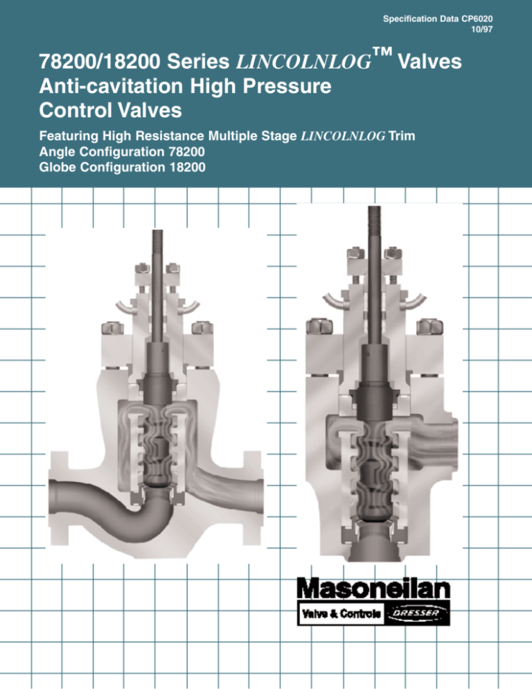
78200/18200 Series LINCOLNLOG™ Valves
Anti-cavitation High Pressure
Control Valves
Featuring High Resistance Multiple Stage LINCOLNLOG Trim
Angle Configuration 78200
Globe Configuration 18200
1
SD CP6020 10/97
78200/18200 Series
Table of Contents
Model Numbering System . . . . . . . . . . . . . . . . . . .3
Ratings (ANSI Class) and Connections . . . . . . . . . .3
General Data . . . . . . . . . . . . . . . . . . . . . . . . . . . . .3
Temperature Range/Seat Leakage . . . . . . . . . . . . .4
Flow Coefficients . . . . . . . . . . . . . . . . . . . . . . . . . .4
Trim Details . . . . . . . . . . . . . . . . . . . . . . . . . . . . . .5
Materials . . . . . . . . . . . . . . . . . . . . . . . . . . . . . .6 - 9
Allowable Pressure Drops . . . . . . . . . . . . . . .10 - 11
Dimensions and Weights . . . . . . . . . . . . . . . .12 - 16
Sizing Guidelines . . . . . . . . . . . . . . . . . . . . . . . . .17
Accessories and Options . . . . . . . . . . . . . . . . . . .18
Foreword
The 78200/18200 Series LINCOLNLOG™ valves provide
smooth and accurate capacity control of high pressure drop liquids without cavitation, erosion, vibration and high noise levels
associated with conventional single stage control devices.
High Allowable Pressure Drops
With balanced trim for valve sizes 11/2" through 8", a wide range
of allowable pressure drops is available with conventional spring
diaphragm or piston actuators. Trim and body materials are
available for NACE and corrosive applications.
Masoneilan’s Lincolnlog valve design is based on the principle of
high resistance multistep axial flow trim. In an axial flow trim, fluid
flow is parallel to the axis of the plug and cage. Pressure reduction occurs along the length of the plug; therefore, no individual
stage is ever exposed to the full pressure differential. As a result,
trim life is greatly extended
The unbalanced trim design is suitable for slurry or high temperature services. Valves are provided with large diameter stems
and appropriate actuators, allowing high pressure drops in
unbalanced construction.
The Lincolnlog trim design offers a unique configuration with a
series of equal capacity stages, to control erosion, followed with
last stage expansion to reduce the potential for cavitation. This
valve staging is designed to limit pressure drop per stage, controlling fluid velocity and greatly extending trim life in severe
services.
Because of the relatively large flow passages and shearing
action provided by the multistep plug and cage designs, these
valves are particularly well-suited for applications involving fluids
with entrained particles, a potentially serious problem for other
valve designs which are subject to clogged flow passages.
Good throttling resolution is provided on even small Cvs.
Simple trim construction eliminates maintenance problems and
allows for easy custom design to meet specific applications.
Optional trim staging configurations can be provided for compressible, two-phase, and flashing fluid conditions. A higher
number of stages can be provided for higher ∆P requirements.
Tight Shutoff
Protection against seat erosion is ensured by provision of ANSI
FCI 70.2 Class V seat shutoff when standard metal seats are
furnished. Class VI seat shutoff is available when optional soft
seats are supplied.
© 1997 Dresser Industries, Inc.
All rights reserved.
Variation of Body Configurations
Standard angle or globe body styles with various end connection
configurations are offered to accommodate a variety of piping
requirements. Oversized or reduced end connections are available and face-to-face dimensions may be matched to existing
installations.
Lincolnlog valve bodies are available in cast globe or forged
globe and angle designs. A variety of carbon, low alloy, and high
alloy steels are available.
Typical Applications
Power Industry
Boiler feed pump recirculation
Desuperheater spray nozzle control
Labyrinth pump seal pressure control
Feedwater start-up regulators
Economizer bypass
Oilfield
Water injection pump recirculation
Produced/waste water injection well control
H. P. separator letdown
Refinery
H2S contactor letdown (DEA, MEA, Glycol)
Charge pump recirculation
Reactor cold separator letdown
Trade names noted throughout are for reference only. Masoneilan
reserves the right to supply trade named material or its equivalent.
SD CP6020 10/97
78200/18200 Series
Model Numbering System
2nd
1st
1st
2nd
3rd
8
2
Actuator Type
Series
Trim Type
20 Handwheel
84 Cylinder: Spring return,
direct, air to close
(fail open action)
85 Cylinder: Spring return,
reverse, air to open
(fail closed action)
86 Double Acting Cylinder
Air to extend
Air to retract
87 Spring Diaphragm
direct, air to close
(fail open action)
88 Spring Diaphragm
reverse, air to open
(fail closed action)
1. Globe
7. Angle
2. Axial Flow
High
Resistance
4th
No. of Stages *
3. Three
4. Four
6. Six
Trim Size
0.
1.
2.
* More stages are available for specific service.
Please consult Masoneilan.
5th
3.
4.
5.
6.
7.
8.
9.
Optional Trim
Trim A, Balanced
Hard Seat
Trim B, Balanced
Hard Seat
Trim C, Balanced
Hard Seat
Trim A, Balanced
Soft Seat
Trim B, Balanced
Soft Seat
Trim C, Balanced
Soft Seat
Trim A, Unbalanced
Hard Seat
Trim B, Unbalanced
Hard Seat
Trim C, Unbalanced
Hard Seat
Ratings (ANSI Class) and Connections
Size
❑
●
∆
■
▼
(in.)
Threaded
Socket Weld*
Butt Weld*
RF Flange
RTJ Flange
* Pipe nipples and
reducers can be
provided.
ANSI
600
900
1500
2500
1 and 11/2
❑●∆■▼
❑●∆■▼
❑●∆■▼
❑●∆■▼
2
❑●∆■▼
❑●∆■▼
❑●∆■▼
❑●∆■▼
3
∆■▼
■▼
∆■▼
∆■▼
4
∆■▼
■▼
∆■▼
∆■▼
6
∆■▼
■▼
∆■▼
∆■▼
8
∆■▼
■▼
∆■▼
∆■▼
Note: Other flange ratings and end connections are available.
General Data
• Trim
• Body
type:
flow direction:
Cv ratio:
1" through 8" forged angle
1" through 6" forged globe
2" through 8" cast globe (3- and 4-stage)
flow to open (flow to close optional)
see flow coefficient table
on page 4
• Bonnet
type:
type:
characteristic:
multiple step axial flow
modified linear
• Actuator
type:
conventional multi-spring diaphragm,
spring piston, throttling piston,
manual handwheel
stud bolted
For other types of actuators, please consult Masoneilan.
3
SD CP6020 10/97
78200/18200 Series
Temperature Range/Seat Leakage
Size
(in.)
Design
1
11/2 - 8
Minimum
Temperature Range
Maximum
Seat Leakage
ANSI FCI 70.2 Class
Unbalanced
Metal Seat
-20°F
+500°F
V
Standard
Balanced
Metal Seat
-20°F
+450°F
V
Optional
Unbalanced
Metal Seat
-20°F
+500°F
Optional
Soft Seat
-20°F
+450°F
2-8
VI
Note: Other designs for higher and lower temperatures are available. Please contact Masoneilan
Flow Coefficients: Rated Cv, Critical Flow Factor - FL and Minimum Controllable Cv
Standard Capacity Trim
Size
(in.)
Orifice
Diameter
(in.)
3-Stage
Travel
(in.)
C
4-Stage
A
Min.
Cont.
6-Stage
B
C
A
Min.
Cont.
Cv
FL
Cv
Cv
FL
Cv
FL
Cv
FL
Cv
B
C
Min.
Cont.
Cv
FL
Cv
FL
Cv
FL
Cv
1
.70
.25
2.0
.98
.05
1.0
.996
1.4
.994
1.7
.991
.04
.80
.998
1.0
.997
1.4
.994
.03
11/2
1.00
.25
3.8
.98
.10
1.9
.996
2.5
.994
3.2
.991
.08
1.4
.998
1.8
.997
2.5
.994
.05
2
1.50
.38
9.0
.98
.15
4.5
.996
6.0
.994
7.5
.991
.12
3.5
.998
4.5
.997
6.0
.994
.08
3
2.25
.62
20.0
.98
.25
10.0
.996
13.0
.994
16.5
.991
.20
7.5
.998
9.5
.997
13.0
.994
.13
4
2.88
.75
34.0
.98
.43
16.5
.996
22.0
.994
28.0
.991
.35
12.0
.998
16.0
.997
22.0
.994
.22
6
4.12
1.00
65.0
.98
.56
34.0
.996
45.0
.994
56.0
.991
.46
25.0
.998
35.0
.997
45.0
.994
.30
8
5.38
1.25
135.0
.98
1.0
70.0
.996
90.0
.994
115.0
.991
.80
50.0
.998
65.0
.997
91.0
.994
.65
Note: FL is only a function of trim selection and is constant over the full valve travel.
% Max Opening
5
10
20
30
40
50
60
70
80
90
100
% Max Cv
➀
➀
3
15
27
39
52
64
76
88
100
➀ = Clearance flow only.
4
SD CP6020 10/97
78200/18200 Series
Trim Details
Characteristics
The Lincolnlog trim has a basic linear control characteristic.
The trim is designed for “clearance” flow capacity over 15% of
the initial valve travel.
The multistage “clearance” flow design has been introduced
intentionally to avoid high pressure drops in the seating area during throttling at low capacity. This feature extends the shutoff
capability significantly and has a positive influence on the throttling control capability at low capacity of this design.
Lincolnlog Cv vs. Travel
The 15 to 100% of the plug travel provides smooth, accurate and
continuous capacity control.
Controllability extends from maximum Cv value to minimum controllable Cv and provides a controllable turndown of 50:1 for all
except the smallest sizes.
Lincolnlog Trim Overlap
Seat Protection and Cv vs. Travel
0 - 15% of Plug Travel
Trim overlap with the valve in
the closed or low lift positions.
15 - 100% of Plug Travel
There is much greater flow area
through the valve seat than plug
notches. As the result, pressure drop and velocities across
the critical seating surfaces are
controlled eliminating seat damage.
Soft Seat Design (Available in 2" - 8" Sizes)
The “sliding collar” soft seat is a patented Masoneilan design feature. In combination with the 15% trim overlap design in flow to
open direction, it will provide long term shutoff capability and minimal maintenance.
Fluid pressure pushes the collar up to protect the elastomer seat
when the valve is throttling. The “reservoir” of filled PTFE material compensates for wear of the seat as well.
Soft Seat Option
5
SD CP6020 10/97
78200/18200 Series
Valve Sizes 1" and 11/2"
1" Unbalanced Plug with
Integral Seat Design
Heavy Duty “U” Seal
11/2" Balanced Plug Design
with Integral Seat Design
6
SD CP6020 10/97
78200/18200 Series
Materials - Valve Sizes 1" and 11/2"
Temperature: -20°F to +450°F (500°F for Unbalanced)
Ref.
No.
1
2
3
4
5
6
7
8
9
12
13
14
15
16
17
Description
Plug with Integral Stem
Packing Flange Stud
Packing Flange Nut
Packing Flange
Packing Follower
Packing Set
Bonnet
Body Stud
Body Stud Nut
Bonnet Gasket
Body
Seal Retainer
Seat Ring Gasket
Balance Seal
Liner with Integral Seat
Standard Materials
410 St. St. ASTM 479
Alloy Steel ASTM A193 Gr B7
304 St. St. ASTM A194 Gr 8
Carbon Steel
303 St. St. ASTM A582
TFE V-Ring (Crane 285K and Flexible Graphite Optional)
Carbon Steel ASTM A105
Alloy Steel ASTM A193 Gr B7
Alloy Steel ASTM A194 Gr 2H
304 St. St. with Flexible Graphite Filler
Carbon Steel ASTM A105
316 St. St. ➀
304 St. St. with Flexible Graphite Filler
Carbon-Graphite Filled PTFE ➀
17-4 PH Condition H900
Materials for NACE or Sour Gas Service
Temperature: -20°F to +450°F (500°F for Unbalanced)
Ref.
No.
1
2
3
4
5
6
7
8
9
12
13
14
15
16
17
Description
Plug with Integral Stem
Packing Flange Stud
Packing Flange Nut
Packing Flange
Packing Follower
Packing Set
Bonnet
Body Stud
Body Stud Nut
Bonnet Gasket
Body
Seal Retainer
Seat Ring Gasket
Balance Seal
Liner with Integral Seat
Optional Materials
17-4 PH Condition H-1150M
Alloy Steel ASTM A193 Gr B7
304 St. St. ASTM A194 Gr 8
Carbon Steel
303 St. St. ASTM A582
TFE V-Ring (Crane 285K and Flexible Graphite Optional)
Carbon Steel ASTM A105
Alloy Steel ASTM A193 Gr B7
Alloy Steel ASTM A194 Gr 2H
304 St. St. with Flexible Graphite Filler
Carbon Steel ASTM A105
316 St. St. ➀
304 St. St. with Flexible Graphite Filler
Carbon-Graphite Filled PTFE ➀
Nitronic 50 ASTM A479 XM-19
Note: Alternate materials available depending on application requirements.
➀ Seal and retainer not required on 1" valves.
7
SD CP6020 10/97
78200/18200 Series
Valve Sizes 2", 3", 4", 6", and 8"
Cast Globe Body
Available in 2", 3", 4", 6", and 8"
4-Stage
Forged Angle Body
2" Design
➤
Soft Seat
Forged Angle Body
3" through 8"
8
SD CP6020 10/97
78200/18200 Series
Materials - Valve Sizes 2", 3", 4", 6" and 8"
Temperature: -20°F to +450°F (500°F for Unbalanced Hard Seat)
Ref. No.
1
2
3
4
5
6
7
8
9
10
11
12
13
14
15
16
17
18
19a
19b
Description
Stem
Packing Flange Stud
Packing Flange Nut
Packing Flange
Packing Follower
Packing Set
Bonnet
Body Stud
Body Stud Nut
Bonnet Flange
Plug Pin
Metal Seal
Body
Seal Retainer
Bonnet Gasket
Seat Ring Gasket
Balance Seal
Liner/Cage
Plug
Seat Ring
Seat Ring (Soft Seat)
Standard Materials
17-4 PH Condition H-1150M
Alloy Steel ASTM A193 Gr B7
304 St. St. ASTM A194 Gr 8
Carbon Steel
303 St. St. ASTM A582
TFE V-Ring (Crane 285K or Flexible Graphite Optional)
Carbon Steel ASTM A105 Forged
Alloy Steel ASTM A193 Gr B7
Alloy Steel ASTM A194 Gr 2H
Carbon Steel ASTM A516 Gr 70
300 Series St. St.
17-4 PH Condition H-1150M (2" size, 304 St. St. with Flexible Graphite Filler)
Carbon Steel ASTM A105 Forged (A216 WCB Cast)
316 St. St.
304 St. St. with Flexible Graphite Filler
304 St. St. with Flexible Graphite Filler
Carbon-Graphite Filled PTFE
17-4 PH Condition H900
410 St. St. ASTM A479
316 St. St. with Hardface
17-4 St. St. Condition H-1150M with Filled PTFE Seal
Materials for NACE or Sour Gas Service
Temperature: -20˚F to +450˚F (500˚F for Unbalanced Hard Seat)
Ref. No.
1
2
3
4
5
6
7
8
9
10
11
12
13
14
15
16
17
18
19a
19b
Description
Stem
Packing Flange Stud
Packing Flange Nut
Packing Flange
Packing Follower
Packing Set
Bonnet
Body Stud
Body Stud Nut
Bonnet Flange
Plug Pin
Metal Seal
Body
Seal Retainer
Bonnet Gasket
Seat Ring Gasket
Balance Seal
Liner/Cage
Plug
Seat Ring
Seat Ring (Soft Seat)
Optional Materials
17-4 PH Condition H-1150M
Alloy Steel ASTM A193 Gr B7
304 St. St. ASTM A194 Gr 8
Carbon Steel
303 St. St. ASTM A582
TFE V-Ring (Crane 285K or Flexible Graphite Optional)
Carbon Steel ASTM A105 Forged
Alloy Steel ASTM A193 Gr B7
Alloy Steel ASTM A194 Gr 2H
Carbon Steel ASTM A516 Gr 70
300 Series St. St.
17-4 PH Condition H-1150M (2" size, 304 St. St. with Flexible Graphite Filler)
Carbon Steel ASTM A105 Forged (A216 WCB Cast)
316 St. St.
304 St. St. with Flexible Graphite Filler
304 St. St. with Flexible Graphite Filler
Carbon-Graphite Filled PTFE
Nitronic 50 ASTM A479 XM-19
17-4 PH Condition H-1150M
316 St. St. with Hardface
17-4 St. St. Condition H-1150M with Filled PTFE Seal
Note: Alternate materials available depending on application requirements.
9
SD CP6020 10/97
78200/18200 Series
Allowable Pressure Drops (psi)
Models 87 and 88 Spring Diaphragm Actuators
Temperature:
Flow Direction:
Trim:
Metal Seat:
Soft Seat:
Valve
Size
(in.)
1
11/2
2
3
4
6
-20°F to +450°F (500°F)
Flow to Open
Unbalanced (1") Balanced (11/2" - 6") ➀
Seat Leakage per ANSI FCI 70.2 Class V (1" - 6")
Seat Leakage per ANSI FCI 70.2 Class VI (2" - 6")
87 Multi-Spring Actuator
Air to Close
Travel
(in.)
Actuator
Size
88 Multi-Spring Actuator
Air to Open
Air
Supply
(psig)
Spring
Range
(psig)
∆P
Shutoff
(psi)
Air
Supply
(psig)
Spring
Range
(psig)
∆P
Shutoff
(psi)
6
40
60
6 - 14
6 - 14
1600
4750
50
38 - 45
3325
10
40
60
6 - 14
6 - 14
4375
6250
50
38 - 45
6250
6
40
60
6 - 14
6 - 14
1075
6250
50
38 - 45
4950
10
40
6 - 14
6250
50
38 - 45
6250
10
60
6 - 17
4800
50
34 - 45
2750
16
40
60
6 - 17
6 - 17
3375
6250
50
34 - 45
6250
16
60
6 - 16
4750
50
35 - 45
2925
23
40
60
6 - 16
6 - 16
2835
6250
50
35 - 45
6025
16
60
6 - 18
3275
50
-
-
23
40
60
6 - 18
6 - 18
1100
6250
50
33 - 45
4425
23
60
6 - 18
3725
50
33 - 45
1550
.25
.25
.38
.62
.75
1.00
➀ Consult factory for unbalanced trim pressure drops or high temperature applications over 450°F.
Spring Diaphragm Positioner Selection: 1" - 11/2" - 2" Moore 750P, 3" - 4" - 6" Masoneilan 4700P, 4700E, or 8012.
10
SD CP6020 10/97
78200/18200 Series
Allowable Pressure Drops (psi)
Models 84 and 85 Spring Cylinder Actuators
Temperature:
Flow Direction:
Trim:
Metal Seat:
Soft Seat:
Valve
Size
(in.)
6
8
-20°F to +450°F (500°F)
Flow to Open
Balanced (6" - 8") ➀
Seat Leakage per ANSI FCI 70.2 Class V (6" - 8")
Seat Leakage per ANSI FCI 70.2 Class VI (6" - 8")
84 Spring Piston Actuators
Air to Close
Travel
(in.)
Actuator
Size
85 Spring Piston Actuators
Air to Open
Air
Supply
(psig)
Spring
Range
(psig)
∆P
Shutoff
(psi)
Air Supply
Min/Max
(psig)
Spring
Range
(psig)
∆P
Shutoff
(psi)
Manual
Over
Ride
154
60
80
100
10 - 12
10 - 12
10 - 12
1200
4450
6250
40 / 80
25 - 29
3225
Hydraulic
Jack
314
40
60
10 - 12
10 - 12
2550
6250
40 / 60
25 - 29
6250
Hydraulic
Jack
154
80
100
10 - 12
10 - 12
3025
6250
40 / 60
25 - 30
3850
Hydraulic
Jack
314
60
80
10 - 12
10 - 12
6250
6250
40 / 60
25 - 30
6250
Hydraulic
Jack
1.00
1.25
➀ Consult factory for unbalanced trim pressure drops or high temperature applications over 450°F.
➁ For air to open action, the actuator must have double acting positioner or use 4-way solenoid for Class V or Class VI shutoff. Without air
on the spring side of the cylinder, the valve shutoff rating is Class III.
Spring Cylinder Positioner Selection: 6" - 8" Moore 750P/750E or Bailey AV1/AV2.
Allowable Pressure Drops (psi)
Model 20 Manual Actuators
Model 20 Manual Actuators
Valve
Size
(in.)
Travel
(in.)
1
Yoke
Size
Actuator
(in.)
Allowable
Pressure
Drop
(psi)
.25
B
12
5300
11/2
.25
B
12
6250
2
.38
C
18
6250
3
.62
D-12
18
6250
4
.75
D-12
18
6250
6
1.00
D-16
18
6250
8
1.25
C/F
C/F
C/F
11
SD CP6020 10/97
78200/18200 Series
Dimensions (in.) and Weights (lbs)
Body Subassembly Forged Configuration (78200 Series)
Angle Style
Size
(in.)
ANSI
Class
1
600 - 2500
Globe Style
End
Conn.
Flg
SW
11/2
Flg
600 - 2500
SW
Flg
600 - 1500
SW
2
Flg
2500
SW
600 - 1500
Flg & BW
2500
Flg & BW
600 - 1500
Flg & BW
2500
Flg & BW
600 - 1500
Flg & BW
2500
Flg & BW
600 -1500
Flg & BW
3
4
6
8
78200 4- and 6-Stage Forged Angle
Stage
4
6
4
6
4
6
4
6
4
6
4
6
4
6
4
6
4
6
4
6
4
6
4
6
4
6
4
6
4
6
A➀
4.50
2.88
5.50
2.88
3.88
4.00
3.88
4.00
4.75
5.25
5.50
6.25
7.25
10.00
C/F
B
2.75
3.75
2.50
3.88
3.25
4.00
2.75
4.12
6.00
7.00
6.00
6.00
6.00
7.00
6.00
6.00
7.75
11.00
7.75
11.00
8.75
12.75
8.75
12.75
11.88
17.38
11.88
17.38
C/F
C/F
C
6.00
6.25
8.81
10.81
8.81
10.81
9.00
9.50
11.50
13.00
13.75
C/F
18200 4- and 6-Stage Forged Globe
Valve
(lbs)
85
95
56
66
110
125
60
88
230
248
188
218
230
248
188
218
290
375
380
480
515
650
665
840
1250
1575
1845
2325
C/F
C/F
Stage
4
6
4
6
4
6
4
6
4
6
4
6
4
6
4
6
4
6
4
6
4
6
4
6
4
6
4
6
4
6
A
B
➀
For Dimensions and
Weights Consult Factory
➀ Butt weld and socket weld valves can be provided with welding nipples/reducers to fit projected line size(s) and
schedule(s).
12
Valve
(lbs)
C
SD CP6020 10/97
78200/18200 Series
Dimensions (in.) and Weights (lbs)
Body Subassembly Cast Configuration (18200 Series)
Flanged
Butt, Socket Weld
or Screwed Ends
18200 3- and 4-Stage Cast Globe
Valve
Size
(in.)
ANSI
Class
600
2
900/
1500
600
3
900
1500
600
4
900
1500
End
Conn.
RF
RJ
SW / BW
RF
RJ
SW / BW
RF
RJ
BW
RF
RJ
SW / BW
RF
RJ
BW
RF
RJ
BW
RF
RJ
BW
RF
RJ
BW
A➀
Stage
14.75
14.88
14.75
14.75
14.88
14.75
17.38
17.50
17.38
17.38
17.50
17.38
18.12
18.25
18.12
20.12
20.25
20.12
20.12
20.25
20.12
20.88
21.00
20.88
3/4
3/4
3/4
3/4
3/4
3/4
3/4
3/4
B
C
Weight
(lbs)
3.60
3.60
3.60
3.60
3.60
3.60
5.25
5.25
5.25
5.25
5.25
5.25
5.25
5.25
5.25
7.20
7.20
7.20
7.20
7.20
7.20
7.20
7.20
7.20
11.50
11.50
11.50
11.50
11.50
11.50
16
16
16
16
16
16
16
16
16
19
19
19
19
19
19
19
19
19
150
150
120
175
175
130
250
250
200
325
325
250
350
350
250
450
450
390
550
550
460
590
590
460
➀ Butt weld and socket weld valves can be provided with welding nipples/reducers to fit projected line
size(s) and schedule(s).
13
SD CP6020 10/97
78200/18200 Series
Dimensions (in.) and Weights (lbs)
Model 87/88 Spring Diaphragm Actuator
Shown with optional handwheel
Model 87/88 Spring Diaphragm Actuator Dimensions (in.)
Actuator
Size
E
F
G
H
6
11.50
15.54
10.00
9.00
10
14.50
19.58
10.90
12.00
16
18.75
28.22
13.00
18.00
23
21.63
30.71
15.00
18.00
Weights (lbs)
Actuator
Size
Standard
w/Handwheel
6
45
60
10
85
105
16
195
245
23
260
320
14
SD CP6020 10/97
78200/18200 Series
Dimensions (in.) and Weights (lbs)
Model 84, 85, 86 Cylinder Actuators
Hydraulic manual
override can be
remote mounted
Shown with optional hydraulic manual override
For 154 sq. in. and 314 sq. in. actuator only
Model 84, 85 and 86 Cylinder - Direct, Reverse and Double Acting Dimensions (in.)
Actuator
Size
E
F
G
H
154 sq. in.
18.1
47.8
26.7
60.5
314 sq. in.
23.9
49.8
27.0
62.5
Medium
Spring
Large
Spring
Manual
Override
Note: Actuator removal clearance = 6 inches
Weights (lbs)
Actuator
Size
Base
Weight
Small
Spring
154 sq. in.
266
60
-
82
100
314 sq. in.
709
60
84
142
100
Nominal Spring Range
154 sq. in.
-
10 - 20
-
15 - 30
-
314 sq. in.
-
5 - 10
7.5 - 15
12.5 - 25
-
15
SD CP6020 10/97
78200/18200 Series
Model 20 Manual Handwheel
D Yoke
B and C Yoke
Model 20 Manual Actuator Dimensions (in.)
Valve
Size (in.)
Yoke
Size
E
F
1
1
1 /2
B
12
9.0
B
12
9.0
2
C
18
11.2
3
D-12
18
14.0
4
D-12
18
14.0
6
D-16
18
20.5
8
C/F
C/F
C/F
Weights (lbs)
Handwheel with Standard Yoke
B
15
C
32
D-12
50
D-16
80
16
SD CP6020 10/97
78200/18200 Series
LINCOLNLOG™ Valve Sizing Guidelines
Lincolnlog multistep control valves can be sized using standard
ISA equations, the sizing procedures from Masoneilan Sizing
Handbook, or the computer sizing program furnished by
Masoneilan.
Noise calculations are best performed by using the computerized
program. The serial stage configuration of the Lincolnlog design
reduces valve trim noise significantly. The actual valve noise can
be approximated by calculating the last stage noise, using the
standard noise calculation procedures. The ∆P of the last stage
for approximate noise calculating can be derived from the table
below.
Selection of the correct trim can be made by determining the
∆P/stage from the table below. It is good practice to limit the
∆P/stage to 800 psi for continuous duty cycle and to 1000 psi for
intermittent duty. The resulting recommended ∆P throttling is
shown in the same table.
For flashing flow conditions, the expansion ratio of the fluid shall
approximate the staging ratio of the selected trim. Nonstandard
staging ratios for compressible, two-phase or flashing conditions
can be provided. Please consult factory.
For proper sizing of two-phase and flashing fluid, the inlet and
outlet density of the fluid needs to be determined.
Lincolnlog Pressure Drop Distribution and Recommended Maximum Pressure Drop
Trim
Type
No. of
Stages
Staging
Ratio
C
3
1-1-2
∆P Fraction
per Stage
.44 Stage 1 to 2
Continuous
Operation
Intermittent
Operation
1800
2250
.11 Stage 3
C
4
1-1-1-2
.31 Stage 1 to 3
.08 Stage 4
2600
3250
B
4
1-1-2-3
.42 Stage 1 and 2
.11 Stage 3
.05 Stage 4
1890
2360
A
4
1-1-2-4
.43 Stage 1 and 2
.11 Stage 3
.03 Stage 4
1850
2325
C
6
1-1-1-1-1-2
.19 Stage 1 to 5
.05 Stage 6
4225
5260
B
6
1-1-1-1-2-3
.23 Stage 1 to 4
.06 Stage 5
.025 Stage 6
3500
4375
1-1-1-1-2-4
.23 Stage 1 to 4
.06 Stage 5
.014 Stage 6
3450
4300
A
6
17
SD CP6020 10/97
78200/18200 Series
Accessories and Options
Accessories
87/88 Actuators
(See Specification Data CR8788)
84/85/86 Cylinders
(See Instruction ER8485)
4700P/4700E Series Positioner
(See Instruction ES2004 and Supplement to
ES2004)
Instrument Signals
3-15 and 6-30 psi
87/88 Actuators
3" - 6" Valves
750P Series Positioner
Moore 750P Single or Double Acting Positioner
Instrument Signals
3-15 psi and 6-30 psi
Split Range
87/88 Actuators
1" - 6" Valves
84/85/86 Actuators
1" - 8" Valves
2700 Controllers
(See Specification Data CW6000)
80-4 or 80-40 Airset
(See Specification Data CY7800)
77-6 Lockup Valve
(See Specification Data CY7700)
77-8 Transfer Valve
(See Specification Data CY8000)
2" Gauge Various Ranges
Solenoid Valves
ASCO, Versa, Westlock and Others
Options
Environmental Capabilities (LE Packing)
8012 Electropneumatic Valve Positioner
(See Specification Data CS5000)
Instrument Signals
10-50 mA, 104 ohms
4-20 mA, 173 ohms
87/88 Actuators
3" - 6" Valves
Body Drain Plug
Other Materials
Other Flange Facings, Graylok
NACE Compliance
Custom Trim Materials
Nondestructive Examination
7000 Electropneumatic Transducer
(See Instruction ES6700)
Input Range
4-20 mA, 550 ohms
Split range up to 3 times
Output
(Direct or Reverse)
3-15 psi, adjustable to 0-20
Volume Tank - Trip System
Electric and Electro-Hydraulic Actuators
Double Acting Cylinder Actuators
154 sq. in., 314 sq. in., 200 sq. in., 400 sq. in., 1000
sq. in.
Snubber Mechanism for Cylinder Actuators
Extension Bonnets
496 Rotary Electric Switches
496-1 (1-Switch SPDT)
496-2 (2-Switches SPDT)
496-3 Position Transmitter
496-6 (1-Switch DPDT)
496-7 (2-Switches DPDT)
(See Specification Data CS7000)
Quick Response Unit
Hydraulic Manual Override (Cylinder Actuator)
Bailey AV 1/2/3/ Single and Double Acting
Positioners
for Cylinder or Domotor Operators
High Pressure / Low Temperature Rating
For additional Accessories and Options, consult the
Masoneilan factory or your representative.

