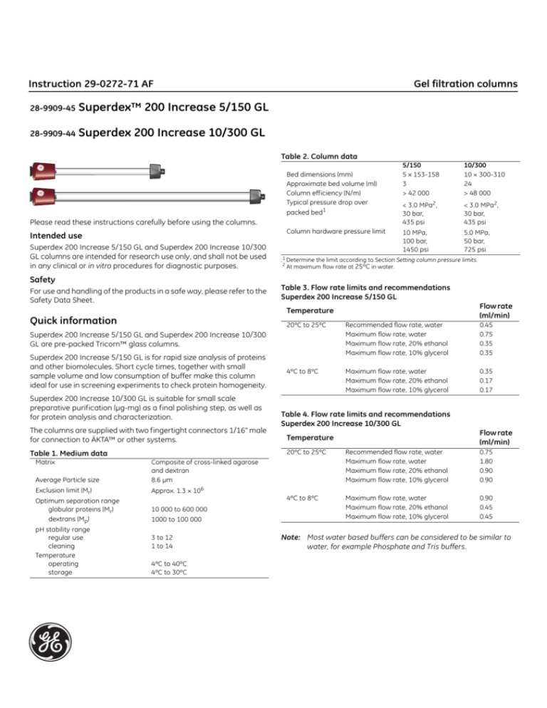
Instruction 29-0272-71 AF
28-9909-45
Superdex™ 200 Increase 5/150 GL
28-9909-44
Superdex 200 Increase 10/300 GL
Gel filtration columns
Table 2. Column data
Bed dimensions (mm)
Approximate bed volume (ml)
Column efficiency (N/m)
Typical pressure drop over
packed bed1
Please read these instructions carefully before using the columns.
Column hardware pressure limit
Intended use
Superdex 200 Increase 5/150 GL and Superdex 200 Increase 10/300
GL columns are intended for research use only, and shall not be used
in any clinical or in vitro procedures for diagnostic purposes.
Safety
For use and handling of the products in a safe way, please refer to the
Safety Data Sheet.
< 3.0 MPa2,
30 bar,
435 psi
< 3.0 MPa2,
30 bar,
435 psi
10 MPa,
100 bar,
1450 psi
5.0 MPa,
50 bar,
725 psi
.1 Determine the limit according to Section Setting column pressure limits.
2
At maximum flow rate at 25ºC in water.
Table 3. Flow rate limits and recommendations
Superdex 200 Increase 5/150 GL
Flow rate
(ml/min)
20ºC to 25ºC
Recommended flow rate, water
Maximum flow rate, water
Maximum flow rate, 20% ethanol
Maximum flow rate, 10% glycerol
0.45
0.75
0.35
0.35
4ºC to 8ºC
Maximum flow rate, water
Maximum flow rate, 20% ethanol
Maximum flow rate, 10% glycerol
0.35
0.17
0.17
Superdex 200 Increase 5/150 GL and Superdex 200 Increase 10/300
GL are pre-packed Tricorn™ glass columns.
Superdex 200 Increase 5/150 GL is for rapid size analysis of proteins
and other biomolecules. Short cycle times, together with small
sample volume and low consumption of buffer make this column
ideal for use in screening experiments to check protein homogeneity.
Superdex 200 Increase 10/300 GL is suitable for small scale
preparative purification (µg-mg) as a final polishing step, as well as
for protein analysis and characterization.
The columns are supplied with two fingertight connectors 1/16" male
for connection to ÄKTA™ or other systems.
Table 1. Medium data
Average Particle size
Composite of cross-linked agarose
and dextran
8.6 µm
Exclusion limit (Mr)
Approx. 1.3 × 10⁶
Optimum separation range
globular proteins (Mr)
dextrans (Mp)
10 000 to 600 000
pH stability range
regular use
cleaning
Temperature
operating
storage
10/300
10 × 300-310
24
> 48 000
Temperature
Quick information
Matrix
5/150
5 x 153-158
3
> 42 000
1000 to 100 000
3 to 12
1 to 14
4ºC to 40ºC
4ºC to 30ºC
Table 4. Flow rate limits and recommendations
Superdex 200 Increase 10/300 GL
Flow rate
(ml/min)
Temperature
20ºC to 25ºC
Recommended flow rate, water
Maximum flow rate, water
Maximum flow rate, 20% ethanol
Maximum flow rate, 10% glycerol
0.75
1.80
0.90
0.90
4ºC to 8ºC
Maximum flow rate, water
Maximum flow rate, 20% ethanol
Maximum flow rate, 10% glycerol
0.90
0.45
0.45
Note: Most water based buffers can be considered to be similar to
water, for example Phosphate and Tris buffers.
Instruction 29-0272-71 AF
First time use
Gel filtration columns
Setting column pressure limits
There are two pressure limits to consider when running the column,
the pressure drop over the packed bed and the column hardware
pressure limit. The pressure drop over the packed bed differ for each
column and the limit has to be individually set. Note that it might be
significantly lower compared to the typical value noted in Table 2.
Fig 1. Illustration of how to lock the adapter. The locking ring (black) must be
in the down-position to prevent uncontrolled adjustment of the column's bed height.
Before connecting the column to a chromatography system, make
sure there is no air in the tubing and valves. Remove the storage/
shipping device, see Section Delivery/storage, and the stop plug from
the column. Check that the upper adapter is locked (locking ring
pressed down, see Fig. 1). Make sure that the column inlet is filled with
liquid and connect it drop-to-drop to the system. For maximum
resolution especially on the 5/150 column, minimize dead volumes
between the injection valve and the column as well as between the
column outlet and the detector.
Exceeding any pressure limit may lead to collapse of the gel bed or
damage to the column hardware. Increased pressure is for example
generated when running/using one or a combination of the following
parameters:
•
•
•
Eluent or sample with high viscosity compared to water
Low temperature compared to room temperature
Modifications to the flow path, for example changing to thinner/
longer tubing
For optimal functionality it is important to know the pressure drops
over different parts of your system and how they affect the column.
All ÄKTA chromatography systems measure pressure at the system
pump, ppump (see Fig. 2). Some systems have additional pressure
sensors located before and after the column, ppre-c and ppost-c.
Prepare the column for first-time use as follows:
Pressure drop
Note: Buffer solution, column and system should be kept at the same
temperature when operating.
õpbefore = 0.5 MPa
a) Equilibrate with at least 2 column volumes (CV) of room tempered
water at a flow rate of 0.30 ml/min (5/150) or 0.75 ml/min (10/300).
b) Set pressure limits for the column in your method according to
Section Setting column pressure limits.
Back pressure
ppump = 4.5 MPa
ppre-c = 4.0 MPa
õp = 3.0 MPa
c) Equilibrate with at least 2 CV eluent at a flow rate of
0.30 ml/min (5/150) or 0.75 ml/min (10/300).
ppost-c = 1.0 MPa
d) It is recommended to perform a column performance control for
future comparisons, see Section Column performance control.
NOTICE
Make sure to not exceed the pressure limits of the
column. Take extra care when working at low
temperatures, like in a cold room, or when the column
is used with 20% ethanol or other viscous solutions. Decrease the
flow rate according to Table 3 or 4. Set pressure limits according to
Section Setting column pressure limits.
Pump
õpafter = 1.0 MPa
poutlet = 0 MPa
Fig 2. Example of the pressure in different parts of a system during run of a
column.
•
•
•
Δpbefore does not affect the column.
The pressure on the column hardware is the sum of
Δpafter and Δp (on some systems monitored separately as
ppre-c). Do not exceed the column hardware limit!
Δp, is individual for each column and needs to be determined.
For more information, please refer to the ÄKTA laboratory-scale
Chromatography Systems Instrument Management Handbook.
2
Instruction 29-0272-71 AF
How to set pressure limit for ÄKTAexplorer, ÄKTApurifier,
ÄKTAmicro, and other systems with a pressure sensor in the
pump
Gel filtration columns
2
Connect the column to the system. Let the flow drip from the
column outlet. The column should be equilibrated in water and at
the temperature for the experimental conditions.
Run the pump at maximum flow rate of the column in water and
at the temperature for the experimental conditions. For exact
values, see Table 3 or 4.
Note the pressure value.
The now measured ppre-c value is the maximum pressure over
the packed bed, Δp (DeltaC pressure).
3
Set the value as Alarm pre column pressure in software.
Determination of column specific pressure drop over the
packed bed, Δp (see Fig. 2):
1
Δpbefore is measured in absence of the column. Run the pump at
maximum flow rate of the column in water and at the
temperature for the experimental conditions. For exact values,
see Table 3 or 4. Let the flow drip from the tubing that will later be
connected to the column. Note the pressure as Δpbefore.
2
Check that the Pressure Alarm in software is set to the same as
the Column hardware pressure limit.
3
Connect the column to the system. Let the flow drip from the
column outlet. The column should be equilibrated in water and at
the temperature for the experimental conditions. Run the pump
at the same flow rate as in step 1. Note the pressure value.
4
Δp is calculated as the pressure value in step 3 minus Δpbefore.
The Δp value will be used in step 8 below.
This Δp value should not be exceeded at any temperature or with
any liquid.
Setting pressure limit in method at your experimental conditions
(intended system setup, flow rate, temperature and eluent):
5
Δpbefore is measured in absence of the column. Run the pump at
your intended flow rate. Let the flow drip from the tubing that will
later be connected to the column. Note the pressure as Δpbefore.
6
Instead of the column, connect a piece of tubing1 to the system.
Run the pump at the same conditions as in step 5. Note the
pressure value as the total system pressure.
7
Δpafter is calculated as the total system pressure value noted in
step 6 minus Δpbefore, noted in step 1.
8
Calculate Δp + Δpafter + Δpbefore.
-
-
If this value is lower than the Column hardware pressure
limit (see Table 2), set the pressure limit in your method as
Δp+Δpafter+Δpbefore.
If Δp + Δpafter exceeds the Column hardware pressure limit,
reduce the flow rate or Δpafter.
Repeat step 4-7.
You can now start your experiment!
How to set pressure limit for ÄKTA pure, without a column
valve or with Column Valve V9-Cs (1 column), and for ÄKTA
avant
This Δp value should not be exceeded at any temperature or with
any liquid!
Setting pressure limit in method at your experimental conditions
(intended system setup, flow rate, temperature and eluent):
4
Δpafter is measured in absence of the column. Run the pump at
your intended flow rate.
5
Instead of the column, connect a piece of tubing1 to the system,
or bypass the column if connected to a valve.
Run the pump at the same conditions as in step 2. The now
measured value is Δpafter.
6
Calculate Δp + Δpafter.
-
If Δp + Δpafter exceeds the column hardware pressure limit,
reduce the flow rate or Δpafter.
Repeat step 4-6.
How to set pressure limit for ÄKTA avant and ÄKTA pure with
Column Valve V9-C (5 columns)
Note: This is not an optimal high performance setup. See Section
“System Recommendations” for more details.
Δp and ppre-c (see Fig. 2) are automatically monitored by the system.
Note: The measured values include the tubing used to connect the
column to the instrument.
1
Check that the Alarm pre column pressure is set to the same as
the Column hardware pressure limit (see Table 2).
2
Connect the column to the system. The column should be
equilibrated in water and at the temperature for the
experimental conditions.
Start running the column at a low flow rate. Slowly increase the
flow until the maximum flow rate for the column under these
conditions or the limit set in step 1 is reached. For exact max flow
rates under different conditions, see Table 3 or 4.
Note the pressure over the packed bed, Δp (delta-column
pressure), and set the value as Alarm Delta column pressure.
Determination of column specific pressure drop over the packed bed
(Δp):
Check that the Alarm pre column pressure in software is set to the
same as the Column hardware pressure limit (see Table 2).
If this value is lower than the Column hardware pressure
limit (see Table 2), set the pressure limit in your method,
Alarm pre column pressure, as Δp + Δpafter.
You can now start your experiment!
ppre-c (see Fig. 2) is automatically monitored by the system. This is the
pressure signal to use in the following instruction. Do not use the
System pressure signal. Note that the measured values include the
tubing used to connect the column to the instrument.
1
-
This Δp should not be exceeded at any temperature or with any
liquid.
You can now start your experiment!
1
Avoid thin and/or long tubing that will give back pressure.
3
Instruction 29-0272-71 AF
Gel filtration columns
Column performance control
In order to detect any changes in column performance, it is very
important that you make an initial test with your particular system
configuration. Note that the contribution from dead volumes in the
instrument to band broadening will vary depending on system set-up
and will influence column efficiency, thus the obtained efficiency on
your system might be lower compared to the specifications in Table 2.
m AU
mAU
60
3
3
60
1
1
2
4
42
5
5
Column efficiency test
Column efficiency, expressed as the number of theoretical plates per
meter, N/m, is calculated using the following equation:
2
40
40
20
20
N/m=5.54 × (VR / Wh) /L
where
N/m
VR
=
=
Wh
=
L
=
number of theoretical plates/meter
volume eluted from the start of sample application to
the peak maximum
peak width measured as the width of the recorded peak
at half of the peak height
bed height (m)
Column Superdex 200 Increase 5/150 GL
100 µl 2% acetone (20 mg/ml) in buffer or water
Buffer or water
1.0 ml/min, room temperature
280 nm
ml
ml
Column Superdex 200 Increase 10/300 GL
Sample:
1. Thyroglobulin (Mr 669 000) 3 mg/ml
2. Ferritin (Mr 440 000) 0.3 mg/ml
3. Aldolase (Mr 158 000) 3 mg/ml
4. Conalbumin (Mr 75 000) 3 mg/ml
5. Ovalbumin (Mr 44 000) 3 mg/ml
6. Carbonic anhydrase (Mr 29 000) 3 mg/ml
7. Ribonuclease A (Mr 13 700) 3 mg/ml
Column Superdex 200 Increase 10/300 GL
Sample:
Eluent:
Flow rate:
Detection:
3.03.0
5/150 GL using ÄKTAmicro.
10 µl 2% acetone (20 mg/ml) in buffer or water
Buffer or water
0.30 ml/min, room temperature
280 nm
Check the performance of the column using the following procedure:
2.0
Fig 3. Typical chromatogram from a function test of Superdex 200 Increase
Check the performance of the column using the following procedure:
Sample:
Eluent:
Flow rate:
Detection:
1.0 2.0
1.0
Sample volume:
Eluent:
Flow rate:
Detection:
100 µl
0.01 M phosphate buffer, 0.14 M NaCl, pH 7.4
0.75 ml/min, room temperature
280 nm
Result is shown in Fig. 4.
Function test
As an alternative to the above efficiency test, check the column
performance by running a function test.
mAU
Column Superdex 200 Increase 5/150 GL.
Sample:
1. Thyroglobulin (Mr 669 000) 3 mg/ml
600
1
6 7
4
2. Aldolase (Mr 158 000) 3 mg/ml
3. Conalbumin (Mr 75 000) 3 mg/ml
4. Carbonic anhydrase (Mr 29 000) 3 mg/ml
10 µl
0.01 M phosphate buffer, 0.14 M NaCl, pH 7.4
0.45 ml/min, room temperature
280 nm
Result is shown in Fig. 3.
5
2
5. Ribonuclease A (Mr 13 700) 3 mg/ml
Sample volume:
Eluent:
Flow rate:
Detection:
3
400
200
10
ml
Fig 4. Typical chromatogram from a function test of Superdex 200 Increase
10/300 GL using ÄKTApurifier.
4
20
Instruction 29-0272-71 AF
Gel filtration columns
Try these conditions first
Eluent:
Chromatogram 10/300 column on different systems
mAU
0.01 M phosphate buffer, 0.14 M NaCl,
pH 7.4
ÄKTAexplorer 10
mAU
75
400
Flow rate:
(room temperature)
0.45 ml/min (5/150);
0.75 ml/min (10/300)
Sample volume:
10 µl (5/150);
100 µl (10/300)
ÄKTA pure
50
200
25
10
Equilibration is not necessary between runs with the same buffer.
Read the Section Optimization for information on how to optimize a
separation.
mAU
20
ml
10
20
ml
ÄKTA avant 25
200
Sample recommendations
100
Molecular weight (Mr):
10 000 to 600 000
Protein concentration:
Up to 50 mg/ml in sample, for higher
resolution below 10 mg/ml.
Sample volume:
10
on different systems. Due to different UV cells for the systems, mAU
scales differ.
Delivery/storage
Dissolve the sample in eluent, filter
through a 0.22 µm filter or centrifuge at
10 000 g for 10 min.
System recommendations
The small bed volume of the 5/150 column makes it sensitive to dead
volumes in the system. For this column it is recommended to use
systems like ÄKTApurifier 10, ÄKTA pure 25 without the column valve
V9-C (5 columns), ÄKTAmicro or similar. Use short, narrow capillaries
and avoid unnecessary components in the flow path.
Note: Be aware of pressure limits.
The 10/300 column has a larger bed volume and can be used in
systems like ÄKTAexplorer 10 and ÄKTA avant 25 in addition to the
systems mentioned above. Consider actions to reduce system dead
volumes if necessary performance is not achieved.
ÄKTA start is not compatible with Superdex 200 Increase columns due
to too low maximum operating pressure.
The column is delivered with a storage/shipping device that prevents
it from drying out. The column is equilibrated with degassed 20%
ethanol.
If the column is to be stored for more than 2 days after use, wash the
column with 2 column volumes (CV) of water and then equilibrate with
at least 2 CV 20% ethanol.
Note: Use a lower flow rate for 20% ethanol.
We recommend that you connect the storage/shipping device
according to Section How to connect the storage/shipping device for
long term storage.
Troubleshooting
Symptom
Increased back-pressure
over the column and/or loss
of resolution.
Chromatogram 5/150 column on different systems
mAU
mAU
ÄKTAmicro
100
ÄKTA pure
75
50
50
Air in the column
25
1.0
2.0
ml
1.0
ml
Fig 6. Comparison of protein separation on Superdex 200 Increase 10/300
4 to 50 µl (5/150)
25 to 500 µl (10/300)
Preparation:
20
2.0
ml
Fig 5. Comparison of protein separation on Superdex 200 Increase 5/150 on
different systems. Due to different UV cells for the systems, mAU scales
differ.
Space between gel bed and
adapter
Remedy
Confirm that the column is the cause (see
below). If so, clean it according to the procedure described in the Section
Cleaning in place (CIP).
To confirm that the high back-pressure in
the system is caused by the column, disconnect one piece of equipment at a time
(starting at the fraction collector) with the
pumps running. Check the pressure
reading after each piece has been disconnected to determine the source of the
back-pressure.
Note that small amounts of air will normally not affect the performance of the
column. Run 3 to 4 column volumes (CV)
of well de-gassed eluent in an
upflow direction at a flow rate of
0.2 ml/min (5/150) or 0.5 ml/min (10/300)
at room temperature.
Turn down the adapter to the gel bed.
Perform a Column performance control.
5
Instruction 29-0272-71 AF
Gel filtration columns
How to remove the storage/shipping device
1
2
3
1
Push down the spring-loaded cap.
2
Remove the locking pin.
3
Release the cap and unscrew the
device.
pH
8.6
Buffer/eluent
6 M guanidine
hydrochloride in
0.05 M Tris-HCl
11.5
0.05 M NaOH
Buffer additives
Up to 8 M urea (pH<7)
How to refill the storage/shipping device
1
2
2
Connect a syringe or pump to the
storage/shipping device and fill with
20% ethanol over the mark on the
tube. Remove the syringe or
connection to the pump.
3
1
2
Fill the column inlet and luer
connector with 20% ethanol and
connect the filled storage/shipping
device drop-to-drop to the top of the
column.
Mount the spring-loaded cap (2) and
secure it with the locking pin(3).
The glass tube is coated with a protecting plastic film. Small
quantities of air may occasionally be trapped between the glass and
the film during manufacture. The resulting uneven surface does not
affect column performance or durability.
Select an eluent that ensures the sample is fully soluble. Also try to
choose an eluent that will simplify downstream applications. For
example, if the proteins/peptides are to be lyophilized, a volatile
eluent is necessary. Since ionic interactions can occur with both
acidic and basic proteins at very low salt concentrations, a
recommended buffer is 0.01 to 0.05 M sodium phosphate with
additional 0.15 M NaCl, pH 7.4. Table 5 lists some useful eluent
compositions.
Table 5. Useful eluent compositions
pH
5.0
Buffer/eluent
0.1 M ammonium acetate
6.8
0.2 M sodium phosphate
7.2
0.05 M phosphate
+ 0.15 M NaCl
0.15 M ammonium
hydrogen carbonate
8.0
6
0.1 M Tris-HCl,
0.001 M EDTA
0.2 M arginine
Good solubility for many components. Biological activity can be
maintained at lower urea contents.
Certain risk for carbamylation of
proteins.
Molecular weight determinations of
subunits.
Good solubility for some proteins,
e.g., membrane proteins. Make sure
you equilibrate completely with the
detergent solution.
Decrease tendency of aggregation.
Buffers and solvent resistance
De-gas and filter all solutions through a 0.22 µm filter. Install an online filter before the injection valve.
Note: Buffers and solvents with increased viscosity will affect the
back pressure. Reduce the flow rate if necessary.
Long term use
Long term use refers to use where the medium is stable over a long
period of time without adverse side effects on its chromatographic
performance.
•
•
•
•
All commonly used aqueous buffers, pH 3 to 12
Urea, up to 8 M
Ionic and non-ionic detergents
Guanidine hydrochloride, up to 6 M
Short term use
Choice of eluent
7.8
0.1% SDS, Tween or similar
Tap out air bubbles and push the
plunger to the mark on the device.
How to connect the storage/shipping
device
1
6 M guanidine hydrochloride
Properties/application examples
Good UV-transparency.
Suitable if there is a need to purify
proteins under denaturing conditions.
Good solubility for some compounds.
Properties/application examples
Good solubility for some enzymes,
e.g., cellulases. Volatile.
Suitable for some antibody separations.
Physiological conditions.
Suitable for some DNA and protein
separations. Volatile. Should be
used fresh.
Very good solubility for DNA and
RNA.
Short term use refers to the use during regeneration, cleaning-inplace, and sanitization procedures.
•
•
•
•
•
•
•
•
•
Acetonitrile, up to 30%
Sodium hydroxide, up to 1 M
Ethanol, up to 70%
Methanol, up to 100%
Acetic acid, up to 1 M
Isopropanol, up to 30%
Hydrochloric acid, up to 0.1 M
Trifluoroacetic acid, up to 10%
Formic acid, up to 70%
Avoid:
•
•
Oxidizing agents
Unfiltered solutions
Instruction 29-0272-71 AF
Gel filtration columns
Optimization
Fig 10. Comparison of protein separation on Superdex 200 Increase 10/300
using different sample volumes.
If your results are unsatisfactory, consider the following actions.
System dead volumes
Flow rate
Action: Decrease system dead volumes.
Action: Decrease the flow rate.
Effect: Improves resolution.
Effect: Improves resolution for high molecular weight components.
The resolution for small components may be decreased.
mAU
mAU
0.75 ml/min
mAU
0.15 ml/min
400
400
200
200
60
60
40
40
20
20
1.0
2.0
3.0
1.0
1.0
ml
2.0
3.0
ml
different flow rates.
2.0
ID 0.15 mm
1.0
ml
2.0
ml
Fig 11. Comparison of protein separation on Superdex 200 Increase 5/150
using different diameters of a 32 cm long capillary connected to the
column.
Fig 7. Comparison of protein separation on Superdex 200 Increase 5/150 at
mAU
mAU
ID 0.5 mm
Organic solvent
mAU
1.50 ml/min
Action: Add organic solvent.
0.25 ml/min
600
600
Effect: Increases solubility of hydrophobic compounds. Changes
selectivity.
400
400
Columns in series (Superdex 200 Increase 5/150)
200
200
Action: Connect two columns in series.
10
ml
20
10
20
ml
ml
Effect: Increases resolution due to increased bed height. Back
pressure will increase. Be sure not to exceed maximum pressure
limits.
Fig 8. Comparison of protein separation on Superdex 200 Increase 10/300 at
different flow rates.
mAU
Sample volume
Action: Decrease the sample volume.
Effect: Improves resolution.
mAU
mAU
50 µl
30
300
Two columns
120
80
80
40
40
4 µl
1.0
2.0
3.0
ml
2.0
4.0
6.0
ml
Fig 12. Comparison of protein separation on one or two Superdex 200
20
200
mAU
One column
120
Increase 5/150 connected in series.
10
100
1.0
2.0
3.0
1.0
ml
2.0
3.0
ml
For more information, please refer to the handbook Gel filtration,
Principles & Methods.
Fig 9. Comparison of protein separation on Superdex 200 Increase 5/150
using different sample volumes.
mAU
mAU
500 µl
2000
100 µl
600
1500
400
1000
200
500
10
20
ml
10
20
ml
7
Cleaning-in-place (CIP)
Perform the following regular cleaning cycle after 10 to 20 separation
cycles.
Note: When performing CIP, reversed flow is recommended.
Regular cleaning:
1
2
Wash the column with 1 column volume (CV) of 0.5 M sodium
hydroxide alternatively 0.5 M acetic acid at a flow rate of
0.13 ml/min (5/150) or 0.5 ml/min (10/300).
Immediately rinse the column with 1 CV water followed by at
least 2 CV eluent at a flow rate of 0.13 ml/min (5/150) or
0.5 ml/min (10/300).
Before the next run, equilibrate the column until the UV baseline and
pH are stable. Check the column according to Section Column
performance control that the performance is restored.
More rigorous cleaning:
•
•
•
•
•
Depending on the nature of the contaminants, one of the
cleaning solutions in the Section Buffers and solvent resistance
may be used. Always rinse with at least 2 CV water after any of
the cleaning solution has been used.
If column performance is not restored, wash the column with
3 CV 0.5 M arginine. Rinse with at least 2 CV water.
If column performance is still not restored, inject a solution of
1 mg/ml pepsin in 0.1 M acetic acid containing 0.5 M NaCl and
leave overnight at room temperature or one hour at 37ºC. After
enzymatic treatment, clean the column according to the
procedure described in the Section Regular cleaning.
Change the filter at the top of the column. (Since contaminants
are introduced with the liquid flow, many of them are caught by
the filter). Instructions for changing the filter are supplied with
the Filter Kit. Perform a regular cleaning as described above.
If necessary, suspend 2 to 3 mm of the top of the gel bed and
remove it with a Pasteur pipette. Adjust the adaptor to eliminate
the space above the gel.
Ordering information
Product
No. per pack.
Code No.
Superdex 200 Increase 5/150 GL
Superdex 200 Increase 10/300 GL
1
1
28-9909-45
28-9909-44
Product
No. per pack.
Code No.
Superdex 200 Increase 3.2/300
Superose 6 Increase 10/300 GL
Superose 6 Increase 5/150 GL
Superose 6 Increase 3.2/300
Gel filtration LMW Calibration Kit
Gel filtration HMW Calibration Kit
1
1
1
1
1
1
28-9909-46
29-0915-96
29-0915-97
29-0915-98
28-4038-41
28-4038-42
Product
No. per pack.
Code No.
Tricorn 10 Filter Kit*
Tricorn 5 Filter Kit*
Filter tool
Fingertight connector, 1/16” male
Tricorn storage/shipping device
1
1
1
10
1
29-0536-12
29-0535-86
18-1153-20
18-1112-55
18-1176-43
Related products
Accessories
* Do not store exposed to daylight.
Literature
Handbook
Code No.
Size Exclusion Chromatography, Principles & Methods
ÄKTA laboratory-scale Chromatography Systems
Instrument Management Handbook
18-1022-18
29-0108-31
For local office contact information, visit
www.gelifesciences.com/contact
GE and GE monogram are trademarks of General Electric Company.
GE Healthcare Bio-Sciences AB
Björkgatan 30
751 84 Uppsala
Sweden
©2013-2015 General Electric Company—All rights reserved.
First published Jan 2013.
www.gelifesciences.com
GE Healthcare Bio-Sciences Corp
800 Centennial Avenue, P.O. Box 1327, Piscataway, NJ 08855-1327, USA
ÄKTA, Superdex and Tricorn are trademarks of General Electric Company or one of its subsidiaries.
All other third party trademarks are the property of their respective owner.
All goods and services are sold subject to the terms and conditions of sale of the company within GE
Healthcare which supplies them. A copy of these terms and conditions is available on request. Contact
your local GE Healthcare representative for the most current information.
GE Healthcare UK Ltd
Amersham Place, Little Chalfont, Buckinghamshire, HP7 9NA, UK
GE Healthcare Europe GmbH
Munzinger Strasse 5, D-79111 Freiburg, Germany
GE Healthcare Japan Corporation
Sanken Bldg. 3-25-1, Hyakunincho, Shinjuku-ku, Tokyo 169-0073, Japan
29-0272-71 AF 03/2015


