Technical - Imbema Controls
advertisement

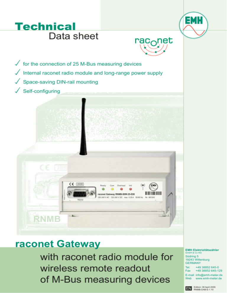
Technical Data sheet for the connection of 25 M-Bus measuring devices Internal raconet radio module and long-range power supply Space-saving DIN-rail mounting Self-configuring RNMB raconet Gateway with raconet radio module for wireless remote readout of M-Bus measuring devices EMH Elektrizitätszähler GmbH & Co KG Südring 5 19243 Wittenburg GERMANY Tel. Fax +49 38852 645-0 +49 38852 645-129 E-mail info@emh-meter.de Web www.emh-meter.de Edition: 08 April 2009 RNMB-DAB-E-1.10 raconet Gateway RNMB for the connection of M-Bus measuring devices Voltage 100...240 V AC (± 10%), 135 V...240 V DC (± 10%) Current max. 0.25 A Frequency 50 Hz, 60 Hz LED-displays Ready COM Overload operate ready communication on the M-Bus LED flashes: bus is overloaded by too much meters LED on: short-circuit LED flashes: initialisation of radio module LED off: initialisation of radio module is finished LED on: error with initialisation of radio module Init Data interfaces M-Bus radio maximum transmission rate acc. to DIN EN 13757-2, -3 raconet radio module 9600 baud Power consumption voltage path <6W Temperature range operation/ limit and storage -25°C...+55°C / -40°C...+70°C Relative humidity 95%, non-condensing acc. to IEC 62052-11, EN 50470-1 and IEC 60068-2-30 Housing dimensions class of protection degree of protection material fire characteristics weight 126 x 90 x 70 (W x H x D) mm, height with antenna = 160 mm 2 IP 20 (higher classes of protection also possible in combination with a meter cabinet) polycarbonate glass-fiber reinforced, without halogen, recycable acc. to IEC 62052-11 approx. 500 g Connection-cross section 2.5 mm² single-wire or fine-wired; 1.5 mm² fine-wired incl. connector sleeve Bus voltage 36 V Version version of antenna max. 25 measuring devices1 internal antenna RNMB-R0W-25-E00 housing antenna RNMB-S0W-25-E00 1 with a standby current of 1.5 mA per device Product specifications are subject to change without notice. Radio (raconet) kWh m³ PSTN, GSM, GPRS, Ethernet Technical Specification M-Bus Bit-transfer from raconet Gateway to Slave (meter) Large wide area installation Network installation Voltage level shifts: log 1 = Vmark = + 36 V log 0 = Vspace = + 24 V Bus-Voltage Vmark = 36 V Vspace = 24 V Dependence on cable diameters, cable lengths and data transfer rates: House installation Small wide area installation Standard GJ M-Bus M-Bus (Metering Bus) is a field bus for the registration of consuming data. Transfer takes place serially on a polarised two-wire cable from the connected meters to the raconet Gateway. The data is usually transferred at a speed from 300 up to 9600 baud. For the cabling no specified topology (winding phase or star) is prescribed. A normal telephone cable, type JYStY N*2*0.8 mm, can be used. Besides for electricity meters the raconet Gateway can be used also for water-, thermal- and gas meters. Type m³ log 1 * log 0 * * The transmission of a logical "0" (Space) by a slave results in a slight reduction in the bus voltage due to output impedance. Max. cable length Cable diameter Data transfer rate 350 m 1 km 0.5 mm² 0.5 mm² 9600 baud 2400 baud 2 km 3 km 0.8 mm² 2400 baud 1.5 mm² 2400 baud 5 km 1.5 mm² 300 baud time Bit-transfer from Slave (meter) to raconet Gateway Bus-Current Imark + 20 mA Imark + 11 mA Imark < 1.5 mA Current admission: Quiescent current: Signal current: Voltage supply: Current lever shifts: log 1 = Imark = < 1.5 mA log 0 = Ispace = Imark + ( 11...20) mA Ispace = Imark + ( 11...20 mA) log 0 log 1 time M-Bus-interface < 1.5 mA < 1.5 mA Imark + (11...20) mA 36 ... 24 V (12 V voltage change between log 1 and log 0)


