Chapter 3: Transformers Single‐Phase Transformer Model
advertisement
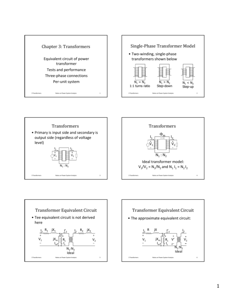
Single‐PhaseTransformerModel Chapter3:Transformers • Two‐winding, single‐phase transformers shown below Equivalent circuit of power transformer Tests and performance Three‐phase connections Per‐unit system 3 Transformers Notes on Power System Analysis 1 3 Transformers V1 V2 Notes on Power System Analysis V1 3 Transformers jXm Im 3 3 Transformers Notes on Power System Analysis 4 TransformerEquivalentCircuit • The approximate equivalent circuit: I1 R I2 R2 jX2 II'2 Ie Rc V2 Ic N1:N2 Ideal Notes on Power System Analysis V2 Ideal transformer model: V1/V2 = N1/N2 and N1 I1 = N2 I2 • Tee equivalent circuit is not derived here V1 I2 N1 : N2 TransformerEquivalentCircuit I1 R1 jX1 m I1 N1 : N2 3 Transformers 2 Transformers • Primary is input side and secondary is output side (regardless of voltage level) I2 N1 < N2 Step-up Notes on Power System Analysis Transformers I1 N1 > N2 Step-down N1 = N2 1:1 turns ratio V1 5 3 Transformers jX jXm Im I2 II’2 Ie V2 Rc V’ Ic 2 N1:N2 Ideal Notes on Power System Analysis 6 1 PhasorDiagramofTransformer V1 Im I’2 V’2 Neglect losses and magnetizing current V1 (R+jX) I1 V’2 I1 jX I1 I1 =I’2 This neglect core loss. How would this change if Im is negligible? How would it change if R is negligible? 3 Transformers Notes on Power System Analysis 7 Three‐PhaseTransformer Connections 9 3 Transformers One‐linediagram Notes on Power System Analysis 20 kV 230 kV 230 kV 13.2 kV G Gen Gen 3 Transformers 10 One‐linediagram • Generator step‐up transformer (delta‐ wye), transmission line, and substation step‐down transformer (delta‐wye). 20 kV 230 kV 8 • Convention: primary‐secondary, so delta‐wye means the delta is on the primary (input) side To avoid confusion, we say a step‐up up • To avoid confusion, we say a step or step‐down transformer bank, or draw one‐line diagrams that show the transformer connections – Wye‐wye connection y y – Delta‐delta connection – Wye‐delta connection – Delta‐wye connection Notes on Power System Analysis Notes on Power System Analysis Three‐phasetransformerbanks • Primary and secondary can be connected in wye or delta: 3 Transformers 3 Transformers L d Load 230 kV 13.2 kV Load Notes on Power System Analysis 11 3 Transformers Notes on Power System Analysis 12 2 Three‐phasetransformers Three‐phasetransformers • One option: connect three single‐ phase transformers in a three‐phase bank • Another option: use a three‐phase Another option: use a three phase transformer (all in one tank) 3 Transformers Notes on Power System Analysis • Three‐phase transformer – Core‐form construction is common in three‐phase transformers of low kVA and kV ratings kV ratings – Shell‐form construction is common in high kVA and kV ratings, and in single‐phase transformers 13 3 Transformers Notes on Power System Analysis Core‐formandshell‐form constructionoftransformers Construction Not to scale • Note that two different winding designs are shown. Single Phase C Core‐Form F Sh ll F Shell‐Form • Either winding design may be used with either shell‐form or core‐form construction. a Three Phase a 14 b c b c 3 Transformers Notes on Power System Analysis 15 Schematicviewofthree‐phase transformerconnections a c b 3 Transformers n’ a c b b’ c’ Notes on Power System Analysis a’ b’ cc’ Delta‐delta connection Wye‐wye connection 3 Transformers 16 Schematicviewofthree‐phase transformerconnections a’ n Notes on Power System Analysis 17 3 Transformers Notes on Power System Analysis 18 3 Delta‐wyeconnections a n’ c b Delta‐wyeconnections a’ b’ c’ Delta‐wye connection (delta leading by 30°). Typical delta‐wye stepdown bank 3 Transformers Notes on Power System Analysis a’ b’ n’ c’’ a c b 19 StandardDelta‐Wye Connection Delta‐wye connection (wye leading by 30°). Typical delta‐wye step‐up bank 3 Transformers Notes on Power System Analysis 20 Three‐phasetransformerbanks • The two connections shown on the previous pages are the standard connections in the US – The high‐voltage side leads the low‐ voltage side by 30°, regardless which side is primary or which side is delta • Many transformers in the real world do not follow the ANSI standard • We assume positive (ABC) phase sequence, or else sign of phase shift is reversed • Delta‐wye transformer banks are common – Local standards may apply 3 Transformers Notes on Power System Analysis 21 3 Transformers Delta‐wyebanks – Provides a neutral on the wye side (usually the secondary but not always) (usually the secondary, but not always). – Isolates the grounds on the secondary from the grounds on the primary. Notes on Power System Analysis 22 Typicalsystem • Delta‐wye transformer banks are common 3 Transformers Notes on Power System Analysis 23 20 kV 230 kV Generator 3 Transformers 230 kV 13.2 kV Transmission Lines Notes on Power System Analysis Distribution Feeders 24 4 Typicalsystem Turnsratioofdelta‐wyebank • Generator grounded through resistor to limit ground fault current • Medium‐voltage distribution circuits solidly grounded at stepdown solidly grounded at stepdown transformer • Relays and circuit breakers at stations and fuses on distribution lines clear heavy faults quickly 3 Transformers Notes on Power System Analysis 25 – Let each single‐phase transformer in a delta‐wye bank have a turns ratio of N1/N2 – The bank “turns ratio” is the line‐line voltage ratio of N1/(3 N2) with a phase shift of 30° with the high‐voltage side leading (phase sequence abc) 3 Transformers Per‐PhaseAnalysis – Represent one phase of equivalent Y, with neutral as return path – Divide all delta impedances by 3 to get equivalent Y impedances – Divide all line‐line voltages by 3 to get equivalent Y line‐neutral voltages – For 3‐phase transformer banks, use ideal transformer with turns ratio equal to nominal line‐line voltage ratio – We may include phase shift due to delta‐wye banks or not, depending on the situation 3 Transformers Notes on Power System Analysis 27 line model j XD/3 / j /6 1:ej/6 20:230 3 Transformers load model j XY ej/6:1 phase shift Notes on Power System Analysis 26 Typicalexample 20 kV 230 kV 230 kV 13.2 kV Gen Load 3 Transformers Notes on Power System Analysis 28 Normalsystem Typicalexample generator model Notes on Power System Analysis 230:13.2 29 • Normal System is one in which the products of the complex voltage ratios of transformer around every loop is 1 – Nominal voltage ratios match up around each loop – Phase shifts are zero around each loop – Many systems are only approximately “Normal Systems” – Deviations are usually small 3 Transformers Notes on Power System Analysis 30 5 Normalsystem Examplesystem 20 kV:230 kV 230kV:44 kV 230kV:46 kV • In a normal system, leave out the phase shifts due to delta‐wye banks (balanced conditions to be analyzed gp p y using per‐phase analysis) Gen 230kV:46 kV Normal system shown. If one of the 230:46 kV transformer ratings is changed to 230:44 kV, then the system would not be normal 3 Transformers Notes on Power System Analysis 31 – The phase of the voltage is shifted the same as the phase of the current, so the power factor is preserved – Warning: remember the phase shift is really there 3 Transformers Non‐NormalSystem – phase shifting transformers used to shift average power loading average power loading – off‐nominal voltage ratios used to shift reactive power loading or to induce changes in voltage magnitude Notes on Power System Analysis 33 Quantity in per unit = actual quantity/base value 3 Transformers Notes on Power System Analysis 34 V1 = Z1 I1 + (N1/N2) V2 and V1/Vb1 = Z1(Ib1/Vb1) (I1/Ib1) + (N1/N2) V2 /Vb1 Let Zb1=Vb Let Zb Vb1/Ib1 and Vb and Vb2=(N (N2/N1)Vb1 Then V1/Vb1 = Z1/Zb1 (I1/Ib1) + V2 /Vb2 V1pu = Z1pu I1pu + V2pu V = Z I where I is in [A], Z in [], and V in [V] Let the base quantities be Ib, Zb, and Vb, also in SI units: V l i SI it Vb = ZZbIb V/Vb = (Z/Zb) (I/Ib) or Vpu = Zpu Ipu Notes on Power System Analysis • It is convenient to use a per‐unit system by normalizing with respect to a base quantity a base quantity Per‐unitequationsoftransformer Per‐UnitSystem 3 Transformers 32 Per‐UnitSystem • In some cases, the system is not be “normal”: 3 Transformers Notes on Power System Analysis 35 3 Transformers Notes on Power System Analysis 36 6 Per‐unitequationsoftransformer Per‐unittransformermodel I1 R I1 = (N2/N1) I2 Let Ib2 = (N1/N2) Ib1 then I1/Ib1 = (N2/N1) I2/Ib1 = I2/Ib2 I1pu = I2pu jX I2 V2 V1 I1 R V1 jX jXm Neglects magnetizing current I2 Includes V2 magnetizing current All quantities in per unit for both circuits 3 Transformers Notes on Power System Analysis 37 3 Transformers Basequantities – Base current Ib = Sb/Vb – Base impedance Zb = Vb/Ib = Vb2/Sb Notes on Power System Analysis 39 – Transformer impedances are usually given in % on a rating base. For example 15% = 0.15 pu means 0.15 x Zb in ohms – Same per Same per‐unit unit value on either side of value on either side of transformer gives different value in ohms since Zb varies as Vb2 3 Transformers • Regardless of whether delta or wye: – Choose base voltages in same ratio as the nominal line‐line voltages – Choose base VA same on both sides h b b h d – Result is the per‐phase equivalent circuit in per‐unit system has no ideal transformer in equivalent circuit – See examples in text Notes on Power System Analysis Notes on Power System Analysis 40 ChangeofBase PerUnitforThree‐Phase 3 Transformers 38 Basequantities • Single‐phase transformer: Base voltage in [V] or [kV] and base apparent power in [kVA] or [MVA] are given: 3 Transformers Notes on Power System Analysis 41 • Changing the base will change the per‐ unit value, but not the actual value in SI units (volts, ohms, amps). Let Z be i in pu: Znew=ZoldZbold/Zbnew Znew=Zold(Vbold2/Sbold)(Sbnew/Vbnew2) Znew=Zold(Sbnew/Sbold)(Vbold/Vbnew)2 3 Transformers Notes on Power System Analysis 42 7 Per‐UnitAnalysisofaNormalSystem – All other base voltages are set by the transformer ratios (rated line‐line voltage ratios) – Express all impedances per unit of the appropriate base, and draw the per‐unit diagram – Solve the problem in per unit, and convert back to SI units • Note that phase shifts due to transformers are often ignored. The procedure follows: – Select a common volt‐ampere base for Select a common volt ampere base for the system – Select one base voltage (usually a nominal or rated voltage in one part of the system) 3 Transformers Notes on Power System Analysis Per‐UnitAnalysisofaNormalSystem 43 3 Transformers Notes on Power System Analysis Per‐unitnetworksforthree‐phase two‐windingtransformers Wye‐wye ZN • Here we discuss only the per‐phase (positive sequence) network for the transformer • Shorthand notation for transformer equivalent circuit is explained below 3 Transformers H Notes on Power System Analysis X VH Y 45 3 Transformers H VH ZX Y ZH VH1 VX ZX Y VX1 Notes on Power System Analysis ZH X VX VH ZN 46 j/6 ZX e :1 Y VX Zn Wye‐delta (typical for delta‐wye stepup with H side leading X side by 30) 3 Transformers ZH Delta‐delta ZX ej/6:1 ZH Zn 44 Notes on Power System Analysis Delta‐wye (typical for delta‐wye stepdown with H side leading X side by 30) 47 3 Transformers Notes on Power System Analysis 48 8 Three‐WindingTransformers Three‐WindingTransformers • Consider the single‐phase three‐ winding transformer shown below I1 • Per unit equivalent circuit: Y represents magnetizing branch, often omitted I2 V2 V1 I1 Z1 V3 3 Transformers Notes on Power System Analysis V1 49 • Measure short‐circuit characteristics of each pair of coils with third coil open Notes on Power System Analysis 51 Three‐phasethree‐winding transformers • Consider a YY connection with both Y's grounded – Per‐phase (positive sequence) networks Per phase (positive sequence) networks are same as that of single‐phase case, with the phase shift to the delta 3 Transformers Notes on Power System Analysis 3 Transformers 53 I3 Z 3 V V2 3 Y Notes on Power System Analysis Z12 = Z1+Z2 Z12 = Z measured at 1 with 2 shorted and 3 open Z13 = Z measured at 1 with 3 shorted and 2 open Z23 = Z measured at 2 with 3 shorted and 1 open 3 Transformers I2 Z2 50 Z13 = Z1+Z3 Z23 = Z2+Z3 Solve for Z1, Z2, Z3 Z1 = (Z12+Z13‐Z23)/2 Z2 = (Z12+Z23‐Z13)/2 Z3 = (Z13+Z23‐Z12)/2 3 Transformers Notes on Power System Analysis 52 Per‐phase (positive sequence) diagram for YY stepdown H = primary (high‐voltage side) Y grounded X = secondary (low‐voltage side) Y grounded T = tertiary (another low‐voltage side) ZX IX IH ZH VH 3 Transformers Ye IT Z T V VX T Notes on Power System Analysis 54 9 • Remarks: – A transformer with a path to ground, besides the high‐impedance magnetizing branch, is a grounding transformer – The YY and Y transformers are grounding transformers, if the Y's are grounded – The YY transformer is not a grounding The YY transformer is not a grounding transformer – The YY and YY transformers pass other system grounds from one side to the other, if the Y's are grounded – The Y and Y isolate grounds 3 Transformers Notes on Power System Analysis 55 Autotransformers • Autotransformers are efficient and economical for voltage ratios above 1:1 and below about 3:1 – Commonly used in Y connections l d – Often have a delta tertiary winding 3 Transformers Notes on Power System Analysis 56 Three‐phaseautotransformer Autotransformers • Widely used to connect systems of different voltage (e.g. 345 kV to 230 kV or 230 kV to 115 kV) • Often has a Y grounded connection Often has a Y grounded connection with a delta tertiary Tertiary 3 Transformers Notes on Power System Analysis – Equivalent circuit is same as YY transformer 57 3 Transformers Notes on Power System Analysis 58 Regulatingtransformersandoff‐ nominaltaps • Transformers that automatically adjust voltage magnitude or phase shift will often have off‐nominal taps – This is not a This is not a “normal” normal system, so ideal system so ideal transformers are not avoided – voltage magnitude changes mainly affect reactive power – phase angle changes mainly affect average power 3 Transformers Notes on Power System Analysis 59 10
