LR25 FLASHCARDS
advertisement
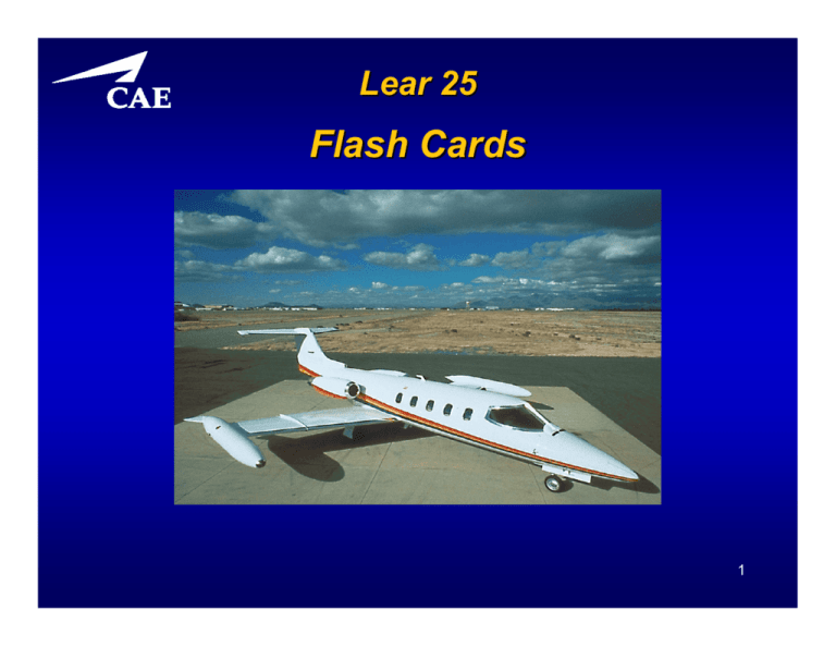
Lear 25 Flash Cards 1 Lear 25 Overview 2 Lear 25 Overview What is the Maximum Demonstrated Crosswind Component? 30.5 Knots 3 Lear 25 Overview What is the Maximum Tailwind Component? 10 Knots 4 Lear 25 Overview What Are the Maximum Load Limits – Flaps Down? 0.0G to +2.0G 5 Lear 25 Overview What Are the Maximum Load Limits – Flaps Up? -1.0G to +3.0G 6 Lear 25 Overview What is the Maximum Recommended Water/Slush for Takeoff and Landing? 0.75 Inch 7 Lear 25 Speeds What is the Turbulence Penetration Speed? 250 KIAS / 0.73MI (Whichever is Less) 8 Lear 25 Speeds What is VMCA – Minimum Control? 102 KIAS 9 Lear 25 Speeds What is VMCG – Minimum Control? 100 KIAS 10 Lear 25 Speeds What is VMO – Sea Level to 14,000 Feet? 306 KIAS 11 Lear 25 Speeds What is VMO – Above 14,000 Feet? 359 KIAS 12 Lear 25 Speeds What is MMO? 0.82MI 13 Lear 25 Speeds What is MMO With Any Missing BLEs? 0.78MI 14 Lear 25 Speeds What is MMO With Autopilot Inoperative? 0.78MI 15 Lear 25 Speeds What is MMO With Stick Puller Inoperative? 0.74MI 16 Lear 25 Altitudes What is the Maximum Airport Pressure Altitude for Takeoff and Landing? 10,000 Feet 17 Lear 25 Altitudes What is the Maximum Enroute Pressure Altitude? 51,000 Feet: With AMK 81-12 45,000 Feet: Without AMK 81-12 18 Lear 25 Weights What is Maximum Ramp Weight? 15,500 Pounds 19 Lear 25 Weights What is Maximum Landing Weight? 13,300 Pounds 20 Lear 25 Weights What is Maximum Takeoff Weight? 15,000 Pounds 21 Lear 25 Weights What is Zero Wing/Tip Fuel Weight? 11,400 Pounds 22 Lear 25 Avionics 23 Lear 25 Avionics What is the Minimum Altitude for Autopilot Use, in Approach Configuration, With the J.E.T. FC-110A AFC/SS? 11,400 Pounds 24 Lear 25 Electrical 25 Lear 25 Electrical What is Maximum Generator Output Limit For All Flight and Ground Operations? Temperatures >60°F: 300 Amps All Other Conditions: 400 Amps 26 Lear 25 Electrical What is the Maximum Amperage Output Limit From a Ground Power Unit? 1,000 Amps 27 Lear 25 Fire Protection 28 Lear 25 Fire Protection What Actions Occur When the Engine Fire Switchlight is Pushed? Fuel and Hydraulic SOVs Close Bleed Air Valve Closes (510 Sys) Fire Bottles Arm Armed Lights Illuminate SOV Lights (Pinhead) Illuminate 29 Lear 25 Flight Controls 30 Lear 25 Flight Controls What is VFE for 8° Flaps? 204 KIAS 31 Lear 25 Flight Controls What is VFE for 20° Flaps? 204 KIAS 32 Lear 25 Flight Controls What is VFE for 40° Flaps? 152 KIAS 33 Lear 25 Fuel 34 Lear 25 Fuel What is the Power Source For the Left Standby Fuel Pump? Left Essential Bus 35 Lear 25 Fuel What Are the Maximum Usable Fuel Quantities (With One Recognition Light)? Wings: 2,320 lbs (1,160 lbs each) Fuselage: 1,305 lbs Tips: 2,430 lbs (Both) Full: 6,055 lbs 36 Lear 25 Hydraulics 37 Lear 25 Hydraulics What is the Duty Cycle of the Electric Hydraulic Pump? 3 Minutes ON – 20 Minutes OFF 38 Lear 25 Ice & Rain 39 Lear 25 Ice & Rain What is the Maximum Recommended Water/Slush for Takeoff and Landing? 0.75 Inch 40 Lear 25 Landing Gear 41 Lear 25 Landing Gear What is VLO (Landing Gear Operating)? 201 KIAS 42 Lear 25 Landing Gear What is VLE (Landing Gear Extended)? 264 KIAS 43 Lear 25 Oxygen 44 Lear 25 Oxygen At What Altitude Will the Passenger Masks Automatically Deploy if Armed? 14,000 Feet 45 Lear 25 Pneumatic 46 Lear 25 Pneumatic Which Systems Are Powered by 8th Stage Bleed Air? Anti-Icing Air Conditioning Hydraulic Tank Pressurization Temperature and Pressurization Vacuum Pressure Regulation 47 Lear 25 Pressurization & Air Conditioning 48 Lear 25 Pressurization & Air Conditioning What is the Maximum Pressure Differential? 10.0 PSI 49 Lear 25 Pressurization & Air Conditioning What Altitude Should the Freon Cooling System Be Selected OFF? FL180 50 Lear 25 Powerplant & Thrust Reversers 51 Lear 25 Powerplant & Thrust Reversers When Must the Engine Sync System Be Turned OFF? Takeoff and Landing Below 70% RPM 52 Lear 25 Powerplant & Thrust Reversers What Are the Operating Limitations of the Ignition System? 2 Minutes ON, 3 Minutes OFF / 2 Minutes ON, 23 Minutes OFF……..OR 5 Minutes ON, 25 Minutes OFF 53 Lear 25 Powerplant & Thrust Reversers What Is Maximum Continuous EGT on the -8A Engine? 724°C 54 Lear 25 Powerplant & Thrust Reversers What Is Maximum Takeoff EGT (5 Minute Limit) on the -8A Engine? 735°C 55 Lear 25 Powerplant & Thrust Reversers What Is Maximum Takeoff EGT (10 Second Limit) on the -8A Engine? 782°C 56 Lear 25 Powerplant & Thrust Reversers What Is Maximum RPM on the -8A Engine? 100% RPM (Observe EGT Limits) 57 Lear 25 Memory Items 58 Lear 25 Memory Items ENGINE FAILURE DURING TAKEOFF BELOW V1 SPEED – ABORT TAKEOFF 1. 2. 3. Thrust Levers - IDLE Wheel Brakes - APPLY Spoilers - EXTEND 59 Lear 25 Memory Items ENGINE FAILURE DURING TAKEOFF Above V1 SPEED – Continue TAKEOFF 1. Rudder/Ailerons – AS REQUIRED FOR DIRECTIONAL CONTROL 2. Accelerate to VR Keep Nose Wheel on Runway to Improve Directional Control 3. Rotate at VR & Climb at V2 At Positive Rate of Climb: 4. Landing Gear - UP When Clear of Obstacles: 5. Accelerate to V2 + 30 & Retract Flaps 60 Lear 25 Memory Items ENGINE SHUTDOWN IN FLIGHT 1. Thrust Lever - CUTOFF 61 Lear 25 Memory Items ENGINE FAILURE DURING APPROACH 1. Control Wheel Master Switch - DEPRESS 2. Thrust (Operating Engine) – INCREASE AS REQUIRED 3. Flaps - 20° MAXIMUM If Configured With Landing Flaps (DN) - Increase Thrust and Retract Flaps Immediately 4. Airspeed – VREF + 10 MINIMUM 62 Lear 25 Memory Items ENGINE FIRE IN FLIGHT - SHUTDOWN 1. 2. Affected Engine – IDENTIFY Thrust Lever – CUTOFF (Unless a Critical Thrust Situation Exists 3. FIRE Warning Light – LIFT GUARD / DEPRESS If Fire Continues: 4. Remaining ARMED Light - DEPRESS If Fire Continues: 5. LAND AS SOON AS POSSIBLE 63 Lear 25 Memory Items T/R INADVERTENT DEPLOYMENT DURING TAKEOFF – BELOW V1 1. Thrust Levers - IDLE 2. Wheel Brakes - APPLY 3. Spoilers - EXTEND 64 Lear 25 Memory Items INDICATION OF T/R DEPLOYMENT DURING TAKEOFF – ABOVE V1 1. Rudder / Ailerons – AS REQUIRED 2. Affected Thrust Lever - IDLE 3. Thrust Reverser Arming Switches - OFF 4. NORMAL-EMER STOW Switch (Affected Engine) – EMER STOW If DEPLOY or UNSAFE Light Remains Illuminated – Stow Unsuccessful 5. ENGINE SHUTDOWN IN FLIGHT Checklist – PERFORM (Pg. e-2) 6. Rotate at VR & Climb at V2 (Increased Rudder/Aileron Necessary Immediately After Liftoff to Maintain Controllability) 7. Gear – UP 8. Flaps - UP 65 Lear 25 Memory Items EMERGENCY DESCENT – CABIN ALTITUDE HORN ACTIVATES OR CABIN ALTITUDE EXCEEDS 10,000 FEET 1. Oxygen Masks – DONN / 100% 2. Thrust Levers - IDLE 3. Autopilot - DISENGAGE 4. Spoiler Switch - EXTEND 5. Gear – DOWN BELOW MMO or VLE (Keep Sideslip to Minimum When Extending Gear) 6. Descend at MMO or VLE – Do Not Descend Below MSA 7. Pass Oxy Valve – NORMAL 8. Pass Mask Valve - MAN 66 Lear 25 Memory Items CABIN/COCKPIT FIRE, SMOKE, OR FUMES 1. Oxygen Masks – DONN / 100% 2. Smoke Goggles (If Available) - DONN 3. PASS OXY / PASS MASK Valves – NORM / MAN 4. OXY-MIC Switches - ON If Source Unknown or Fire Can’t Be Extinguished: 5. LAND AS SOON AS POSSIBLE If Source Known: 5. Extinguish Fire / Eliminate Smoke or Fumes – LAND AS SOON AS PRACTICAL 67 Lear 25 Memory Items PITCH AXIS MALFUNCTION 1. Control Wheel Master Switch – DEPRESS/HOLD 2. Altitude Control – AS REQUIRED 3. Thrust Levers – AS DESIRED 4. STALL WARNING Switches - OFF 5. Pitch Trim Selector Switch - OFF 68 Lear 25 Annunciators 69 Lear 25 Annunciators Flashes when sensing elements in nacelle indicate overheating. Depressing FIRE warning light: Closes Fuel & Hydraulic Firewall Shutoff Valves Shuts Off Bleed Air From Engine (510 Only) Arms Engine Fire Extinguisher System 70 Lear 25 Annunciators Illuminates to indicate fuel level in either wing below 400-500 pounds in level flight. 71 Lear 25 Annunciators Indicates Loss of Fuel Pressure to Designated Engine OR Probable Cause – Jet Pump Failure 72 Lear 25 Annunciators Illuminates to indicate either / both spoilers not down and locked. 73 Lear 25 Annunciators Indicates One or More Cabin Door Locking Pins Not Fully Engaged……OR Lower Door Hooking Mechanism Has Not Been Released 74 Lear 25 Annunciators If STAB & WING HEAT Switch ON: During Flight: Stabilizer Heat Failure On Ground: Normal – Stab Heat Disabled by the Squat Switch 75 Lear 25 Annunciators Indicates Malfunction in Either Pitot Heat System….OR Either Pitot Heat Switch is Selected OFF 76 Lear 25 Annunciators Illumination Indicates Pressure Across Filter Dropped Below Design Value Fuel May Be Bypassing Filter Lack of Anti-Icing Additive May Cause Fuel Filter Icing and Subsequent Engine Flameout 77 Lear 25 Annunciators NAC HEAT Switch ON: OR Indicates Insufficient Bleed Air Pressure in Engine Anti-Ice System for Designated Engine NAC HEAT Switch OFF: Indicates Malfunction of Corresponding Anti-Ice Valve 78 Lear 25 Annunciators Steady Illumination: Indicates OR Malfunction or Loss of Power to Affected Stall Warning System or Pusher Actuation Flashing Illumination: Indicates Actuation of Affected System Shaker 79 Lear 25 Annunciators Illuminates to indicate one wheel of affected vertical gyro has failed. OR 80 Lear 25 Annunciators Indicates affected inverter is OFF or voltage and/or current flow below minimum. OR 81 Lear 25 Annunciators Illumination indicates oil pressure in one/both engines below 5 psi. AND/OR 82 Lear 25 Annunciators Indicates temperature of horizontal stabilizer structure has reached 215°F (102°C). 83 Lear 25 Annunciators In Flight: Indicates Windshield Duct Temperature of 250°F On Ground: Indicates Windshield Duct Temperature of 215°F Green WSHLD HEAT Annunciator Should Be Extinguished 84 Lear 25 Annunciators Illuminates to indicate nosewheel steering engaged on ground. 85 Lear 25 Annunciators Illumination indicates overheat condition in the associated bleed air ducting. OR 86 Lear 25 Annunciators OR Illuminates to indicate affected generator failed… OR is not online due to incorrect voltage… OR generator switch in OFF or START position. 87 Lear 25 Annunciators Indicates cabin altitude above 8,750 ± 250 feet. 88 Lear 25 Annunciators Illumination indicates temperature of wing leading edge has reached 215°F (102°C). 89 Lear 25 Annunciators Normal indication when windshield anti-ice shutoff valves are open. 90 Lear 25 Annunciators Indicates windshield alcohol is low / depleted. 91 Lear 25 Annunciators OR Illuminates to indicate temperature on one or both main electrical system batteries has reached either 140°F or 160°F. 92 Lear 25 Annunciators Illumination indicates nose landing gear is down and locked with Engine Synchronization switch in SYNC. 93 Lear 25 Annunciators Indicates horizontal stabilizer pitch trim setting more than ½° outside takeoff segment on pitch trim indicator. Annunciator does NOT illuminate in flight 94 Lear 25 Annunciators Illuminates to Indicate Hydraulic System Pressure Below Approximately 1,125 to 1,000 PSI Extinguishes When Pressure Rises Above 1,250 PSI 95 Lear 25 Annunciators Indicates fuel crossflow valve is open. 96 Lear 25 Annunciators Illumination indicates affected emergency battery supplying power with normal electrical power failed. 97 Lear 25 Annunciators Illumination in flight indicates trim speed monitor detects trim speed fault which allows high trim speed with flaps up. 98 Lear 25 Part 135 Review 99 Lear 25 Part 131 Review - ATC Where Does the DME Indicator Have the Greatest Error Between Ground and Displayed Distance? At High Altitude – Close to the VORTAC 100 Lear 25 Part 131 Review - ATC Which Checks/Inspections of Flight Instruments or Systems MUST Be Accomplished Before IFR Flight? VOR Within Preceding 30 Days Altimeters/Transponders Within Preceding 24 Months 101 Lear 25 Part 131 Review - ATC What are the Required Items to be Recorded When Performing a VOR Check? Date Place Bearing Error Signature in Aircraft Log or Other Record 102 Lear 25 Part 131 Review - ATC What is the Maximum Speed to be Used in a Procedure Turn? 200 Knots 103 Lear 25 Part 131 Review - ATC If Straight-In Minimums Are NOT Published, May a Pilot Land Straight-In? YES 104 Lear 25 Part 131 Review - ATC When is a Procedure Turn Required? When Necessary to Reverse Direction to Establish the Aircraft Inbound On an Intermediate or Final Approach Course 105 Lear 25 Part 131 Review - ATC Does ATC Retain Wake Turbulence Separation When the PIC Has Accepted Visual Separation From Traffic? NO – Acceptance Also Means the Pilot Accepts Responsibility for Wake Turbulence Separation 106 Lear 25 Part 131 Review - ATC What is the Minimum Climb Gradient to be Maintained Whenever NO Climb Gradient is Specified on a DP (Departure Procedure)? 200 Feet per Nautical Mile 107 Lear 25 Part 131 Review - ATC How Does the LDA Differ From a LOC Course? LDA is Not Aligned Within 3° of Runway 108 Lear 25 Part 131 Review - Meteorology Which Normally Changes When Crossing a Front – Pressure, Temperature, Dew Point, or Wind? Wind 109 Lear 25 Part 131 Review - Meteorology What Conditions Would Be Most Favorable For the Formation of Rime Ice? Light Drizzle Strataform Clouds Temperatures At/Below Freezing 110 Lear 25 Part 131 Review - Meteorology What Conditions Would Be Most Favorable For the Formation of Fog? Light Wind (3-5 Knots) Narrow Temperature/Dew Point Spread (2°C) 111 Lear 25 Part 131 Review - Meteorology What Information Can be Obtained From the 250 Milibar Chart? Winds Aloft at 39,000 Feet 112 Lear 25 Part 131 Review - Meteorology Which Atmospheric Factor Causes Rapid Movement of Surface Fronts? Upper Winds Blowing Across the Front 113 Lear 25 Part 131 Review - Meteorology What Condition is Indicated Whenever Ice Pellets Are Encountered During Flight? Freezing Rain at Higher Levels 114 Lear 25 Part 131 Review - Meteorology Which Type of Precipitation Indicates the Presence of Supercooled Water? Freezing Rain 115 Lear 25 Part 131 Review – Severe Weather Which Conditions Are Most Likely to Produce a Microburst? Convective Activity in Very Dry Air 116 Lear 25 Part 131 Review – Severe Weather What Are the Major Hazards of Flying Under the Anvil of a Thunderstorm? Hail Severe Turbulence Lightning 117 Lear 25 Part 131 Review – Severe Weather What is an Indication That a Thunderstorm Has Reached the Mature Stage? Precipitation 118 Lear 25 Part 131 Review – Severe Weather What is a Squall Line and Where Does It Develop? A Non-Frontal, Narrow Band of Active Thunderstorms Which Often Develops Ahead of a Cold Front in Moist, Unstable Air 119 Lear 25 Part 131 Review – Severe Weather What kind of storms are most likely to generate tornadoes? Steady state thunderstorms associated with cold fronts or squall lines 120 Lear 25 Part 131 Review – Severe Weather Which Conditions are Necessary for a LowLevel, Temperature Inversion Windshear? Calm/Light Wind Near Surface Relatively Strong Wind Just Above Inversion 121 Lear 25 Part 131 Review – Severe Weather What Conditions Are Necessary For a Squall to be Reported? Sudden Increase of Wind Speed By At Least 15 Knots Winds Peaking to 20 Knots or More / Lasting a Minute or Longer 122 Lear 25 Part 131 Review – Severe Weather How Long is a Convective Outlook Valid? 24 Hours 123 Lear 25 Part 131 Review – Severe Weather What Tops Level of a Thunderstorm Would Qualify It as Severe? 35,000 Feet 124 Lear 25 Part 131 Review – Severe Weather How Far Should You Avoid a Thunderstorm? 20 Nautical Miles 125 Lear 25 Part 131 Review – Severe Weather How Far Away From Mountains Could You Expect to Find Clear Air Turbulence Associated With Mountain Wave? 5,000 Feet Above the Tropopause 100 Miles or More Downwind From Mountains 126
