MULTIFUNCTION SPOOL VALVE
5/2-5/3
Series
air and solenoid air operated
subbase mounted body
according to ISO 5599/1
541-542-543
Type
ATEX
ISO sizes 1-2-3
Spool valves intended for use in potentially explosive atmospheres
caused by gases, vapours, mists and/or dusts (ATEX directive 94/9/EC)
ISO 5599/1 spool valve size 1
solenoid air operated
ISO 5599/1 spool valve size 2
solenoid air operated
ISO 5599/1 spool valve size 3
solenoid air operated
MULTIFUNCTION
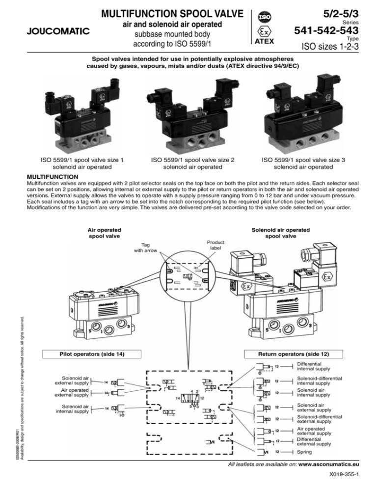
Multifunction valves are equipped with 2 pilot selector seals on the top face on both the pilot and the return sides. Each selector seal
can be set on 2 positions, allowing internal or external supply to the pilot or return operators in both the air and solenoid air operated
versions. External supply allows the valves to operate with a supply pressure ranging from 0 to 12 bar and under vacuum pressure.
Each seal includes a tag with an arrow to be set into the notch corresponding to the required pilot function (see below).
Modifications of the function are very simple. The valves are delivered pre-set according to the valve code selected on your order.
Air operated
spool valve
Solenoid air operated
spool valve
00500GB-2008/R01
Availability, design and specifications are subject to change without notice. All rights reserved.
Tag
with arrow
Pilot operators (side 14)
Product
label
Return operators (side 12)
Differential
internal supply
Solenoid air
external supply
Solenoid-differential
internal supply
Air operated
external supply
Solenoid air
internal supply
Solenoid air
internal supply
Solenoid air
external supply
Solenoid-differential
external supply
Air operated
external supply
Differential
external supply
Spring
All leaflets are available on: www.asconumatics.eu
X019-355-1
ISO 5599/1 SPOOL VALVE SIZES 1-2-3 - SERIES 541-542-543
The table below shows the accessories (delivered with the valves) and/or the solenoid valves appropriate for each function. These components can be
supplied separately to change the function of the valve.
4
2
5
3
12
1
4
14
2
5
12
3
1
14
4
2
5
3
12
1
4
14
2
5
12
3
1
5/2
14
4
2
5
3
12
1
4
14
2
5
12
3
1
14
4
2
5
3
12
1
14
4
2
5
3
12
1
4
2
5
3
12
14
1
5/3
4
2
5
3
12
14
1
return
14
14
pilot (14)
return (12)
symbols
14
pilot
12
Air
operated
Spring
return
●
Air
operated
Differential
return
●
●
Air
operated
Air
return
●
●
●
Solenoid air
operated
Differential
return
●
●
Solenoid air
operated
Air
return
●
●
Solenoid air
operated
Solenoid-differential
return
●
●
Solenoid air
operated
pilot and return
●
●
●
W1-W2-W3
Air
operated
●
W1-W2-W3
Solenoid air
operated
●
●
●
Interface
88100074
Interface
88100074
Solenoid valves
189-190-195-374
Blanking plate
88100073
Turning the selector seal upside
down allows selection between 2
functions (as shown by the arrow).
Internal
supply
External
supply
14
All leaflets are available on: www.asconumatics.eu
12
●
Turning the selector seal upside
down allows selection between 2
functions (as shown by the arrow).
X019-355-2
12
12
Solenoid air
operated
Spring
return
Solenoid valves
189-190-195-374
Internal
supply
12
1
12
External
supply
00500GB-2008/R01
Availability, design and specifications are subject to change without notice. All rights reserved.
function
ISO 5599/1 SPOOL VALVE SIZES 1-2-3 - SERIES 541-542-543
USE WITH NON-LUBRICATED AIR
The ISO-compliant valves will operate satisfactorily with lubricated, non-lubricated or dry air due
to their patented, T-shaped oscillating sealing element backed with a cushioning seal.
This sealing assembly maintains a minimum pilot pressure which remains constant even if the
valve is switched off for a longer period of time. On restart, the valve’s performance will be the
same as under continuous operating conditions.
This characteristic ensures safer operation both on valve start-up and during operation.
MANUAL TESTERS INDICATING THE POSITION OF THE SPOOL (OPTION)
On request, the spool valves can be delivered with manual testers to check the position of the
spool or move it by manual override.
EASY INSTALLATION
ASCO/JOUCOMATIC offers a complementary range of components which simplify the installation of the ISO-compliant valves:
• Single subbases with side or bottom ports (1) - see pages 7 and 9
• Joinable subbases with bottom ports - see pages 8 and 9
Various accessories complete the range - see page 14
00500GB-2008/R01
Availability, design and specifications are subject to change without notice. All rights reserved.
(1)
All leaflets are available on: www.asconumatics.eu
X019-355-3
MULTIFUNCTION SPOOL VALVE
5/2-5/3
Series
solenoid air operated
subbase mounted body
according to ISO 5599/1
541-542-543
ATEX
Type
ISO sizes 1-2-3
GENERAL
• Spool valves intended for use in potentially explosive atmospheres caused by gases,
vapours, mists and/or dusts (ATEX directive 94/9/EC).
CLASSIFICATION
ISO 1-2-3 :
II 2 GD c Ta 60°C T85°C (T6) (zones 1-21)
ISO 1-3 :
II 3 GD c Ta 60°C T85°C (T6) (zones 2-22)
Compliance with the Essential Health and Safety Requirements has been assured by compliance with European Standards EN 13463-1 and prEN 13463-5.
SPECIFICATIONS
Fluid
Operating pressure
Pilot pressure
Ambient temperature
Flow (Qv at 6 bar)
Flow coefficients
ISO 1
ISO 2
ISO 3
Air or neutral gas, filtered, lubricated or not
– 0,950 to +12 bar (with external supply to pilot)
+3 to +10 bar (with internal supply to pilot)
Can be used with vacuum – 0,950 bar max.
See CHOICE OF EQUIPMENT
– 10°C to +60°C
1400 l/min (ANR) 2800 l/min (ANR) 4200 l/min (ANR)
- conforming to ISO 6358
sonic conductance C = 5,8 x 10⁻⁸ m3/s.Pa C = 1,136 x 10–7 m3/s.Pa C = 16 x 10–8 m3/s.Pa
absolute static pressure
b = 0,28
b = 0,22
b = 0,34
- conforming to NF E29312
(l/min)
Life
Base
Subbases
Kv = 20
Kv = 37,5
Kv = 60
30 million cycles
15 million cycles
ISO 5599/1 sizes 1-2-3 - AFNOR NF E49080
Single subbases ISO/AFNOR NF E49085
Joinable subbases ISO/VDMA 24345
CONSTRUCTION
Cover
Pilot and return assembly
Seals
Internal parts
Painted steel
POM (acetal resin)
NBR (nitrile) and PUR (polyurethane)
POM (acetal resin), light alloy
ELECTRICAL CHARACTERISTICS
coil
size
classification
series
II2 GD EEx m II
PV-m22
189
T5..T4
voltage
consumption
inrush holding
~
24V-115V-230V/50Hz
=
24V
4W
9 VA
5 VA (4 W)
series
189
size 22 II3 D IP65 T85°C
à T100°C
DU
~
24V-115V-230V/50 Hz
6 VA 3,5 VA (2,5 W)
=
24V-48V
3W
series
190
size 25 II3 D IP65 T85°C
à T100°C
DU
~
24V-48V-115V-230V/50 Hz
=
12V-24V-48V-110V
3W
series
192*
size 30 II3 D IP65 T85°C
DU
à T135°C
24V-115V-230V/50 Hz
12 VA 6 VA (4 W)
24V
5W
series
374
size 22 II2 GD EEx d IIB
DU
+ H2 T6..T4
~
24V-115V-230V/50 Hz
55 VA 23 VA (10,5W)
=
24V
11,2 W
series
195
size 30 II2 G EEx ia IIC T6 =
24V
9 VA
insulation protection
class
degree
4 VA (3 W)
1,6 W
F
IP 65
F
IP 65
F
IP 65
F
IP 65
F
IP 65
F
IP 65
electrical
connection
moulded-in supply cable,
rotatable on 360°
spade plug size 22 connector,
DIN 43650, 11 mm, industry standard B,
rotatable by 180°
spade plug size 30 connector,
ISO4400/EN175301-803, form A,
rotatable by 90°
spade plug size 30 connector,
ISO4400/EN175301-803, form A,
rotatable by 90°
Screw terminal coil,
explosionproof cable gland on
request
spade plug size 30 connector,
ISO4400/EN175301-803, form A,
rotatable by 90°
Solenoid valve 190 is dual voltage (24V~, 12V=) (48V~, 24V=) (115V~, 48V=) (230V~, 110V=)
* Solenoid valve 192 for ISO 3 only
COIL TEMPERATURE CLASSIFICATION TABLES
Solenoid operators for potentially explosive atmospheres
AC (~) coils, zones 1-21 / 2-22
DC (=) coils, zones 1-21 / 2-22
max. ambient °C 1)
pilot/
coil
surface
temperature
Pn
189 PV 374
T6
T5
T4
T3
(Watt) m22
NK
85°C 100°C 135°C 200°C
Insulation class F (155°C) 100 % E.D.
4
60
•
10,5
60
•
max. ambient °C 1)
pilot/
coil
surface
temperature
Pn
189 PV 374
T6
T5
T4
T3
(Watt) m22
NK
85°C 100°C 135°C 200°C
Insulation class F (155°C) 100 % E.D.
4
25
80
•
11,2
• 25 40 60
1) Minimum ambient temperature: -10°C
All leaflets are available on: www.asconumatics.eu
X019-355-4
DC (=) coils, zones 1 - 2
max. ambient °C 1)
pilot/
coil
surface
temperature
Pn
195
T6
T5
T4
T3
(Watt) size 30
85°C 100°C 135°C 200°C
Insulation class F (155°C) 100 % E.D.
50
1,6
•
00500GB-2008/R01
Availability, design and specifications are subject to change without notice. All rights reserved.
pilot
ISO 5599/1 SPOOL VALVE SIZES 1-2-3 - SERIES 541-542-543
AC (~) coils, zone 22
DC (=) coils, zone 22
max. ambient °C 1)
pilot/
coil
surface temperature
Pn
189
190 192(*)
(Watt) size 22 size 25 size 30 85°C 100°C 135°C 200°C
Insulation class F (155°C) 100 % E.D.
2,5
40
60
•
3
40
60
•
4 (*)
25
60
•
max. ambient °C 1)
pilot/
coil
surface temperature
189
190 192(*)
(Watt) size 22 size 25 size 30 85°C 100°C 135°C 200°C
Insulation class F (155°C) 100 % E.D.
2,5
40
60
•
3
40
60
•
5 (*)
• 25 40 60
Pn
1) Minimum ambient temperature: -10°C
(*) ISO 3 only
CHOICE OF EQUIPMENT
When ordering, please specify: the standard spool valve code and its ATEX option and the solenoid pilot code
function
5/2
solenoid air
pilot (14)
return (12)
symbols
4
14
2
5
12
spring
return
3
1
4
14
2
5
12
differential
return
3
1
air
return
4
14
2
5
12
solenoid-differential
return
3
1
14
4
2
5
3
12
solenoid air
return
1
pilot (14)
00500GB-2008/R02
Availability, design and specifications are subject to change without notice. All rights reserved.
4
2
12
5
1
4
Pressure held
W1
3
2
12
14
5
3
1
4
Pressure applied
W2
2
12
14
5
3
1
de-energized
ISO 1
25
66
3
ISO 2
19
68
2,5
ISO 3
45
130
3
54391023
ISO 1
41
45
3
54191024
ISO 2
32
49
2
ISO 3
71
82
3
Pressure release
W3
10
54292024
ISO 3
28
ISO 1
16
18
3
ISO 2
15
16
2
ISO 3
21
23
3
54391026
ISO 1
17
16
1,5
54191027
ISO 2
16
15
1,5
ISO 3
26
25
1,5
size
54391025
54191026
10
10
54292026
+ 2x
54292027
54391027
2 codes
pilot
pressure
(bar)
spool valve
de-energized
ISO 1
16
17
ISO 2
16
16
ISO 3
27
26
ISO 1
44
18
ISO 2
54
18
ISO 3
93
27
54391029
ISO 1
17
47
54191029
ISO 2
19
61
29
28
● : screwdriver
●
●
✕
●
▼
✕
●
▼
●/▼
✕
●
54292025
energized
✕ : without
PV 18900001
DU 18900001
DU 19000005
DU 19000006
DU 19000017
DU 19200001*
DU 19200002*
DU 19200003*
19500017
NKS374A090
NKS374A090 MS
+ 1x
54191025
10
1,5
min.
(M)
54391024
1,5
response
time
(ms)
with
standard connnector
54292023
21
1,5
quantity and code
54191023
10
16
-
solenoid pilot
+
max.
ISO 1
ISO 3
(M) Type of manual override on pilot(s) :
* Solenoid valve 192 for ISO 3 only
min.
ISO 2
solenoid air
return (12)
symbols
spool valve
energized
function
5/3
14
size
2 codes
pilot
pressure
(bar)
response
time
(ms)
solenoid pilot
+
max.
quantity and code
with
standard connnector
(M)
PV 18900001
DU 18900001
DU 19000005
DU 19000006
DU 19000017
DU 19200001*
DU 19200002*
DU 19200003*
19500017
NKS374A090
NKS374A090 MS
●
●
✕
●
▼
✕
●
▼
●/▼
✕
●
54191028
3
10
54292028
54391028
54191030
3
3
10
10
54292030
+ 2x
54292029
54391030
▼ : impulse
●/▼ : impulse or lock (push-turn type)
OPTIONS
• Equipment with manual testers so that the spool position can be checked
• Equipment for use in potentially explosive atmospheres caused by dusts or gases (ATEX Directive 94/9/EC)
zones
2-22
1-21
classification
II3GD c T 60°C T 85°C (T6)
II2GD c IIC T 60°C T85°C (T6)
ISO 1
612027
612030
ATEX option catalogue number
ISO 2
ISO 3
612029
612090
612032
All leaflets are available on: www.asconumatics.eu
X019-355-5
ISO 5599/1 SPOOL VALVE SIZES 1-2-3 - SERIES 541-542-543
SUBBASES
description
type of subbase
ports
type of connection
12-14
G 1/8
G 1/8
G 1/8
G 1/8
G 1/8
G 1/8
G 1/8
G 1/8
G 1/2
side
tapped
single
subbase
ISO 5599/1
AFNOR NFE 49080
bottom
joinable
subbase
ISO 5599/1
VDMA 24345
bottom
tapped
1
G 1/4
G 1/4
G 3/8
G 3/8
G 1/2
G 1/2
G 3/4
G 1/4
G 3/8
with couplers
Ø 4 mm
subbase
set of 2 end plates
subbase
set of 2 end plates
subbase
set of 2 end plates
G 1/8
G 1/8
G 1/8
-
size
2-4
G 1/4
G 1/4
G 3/8
G 3/8
G 1/2
G 1/2
G 3/4
G 1/4
G 3/8
3-5
G 1/4
G 3/8
G 3/8
G 3/8
G 1/2
G 1/2
G 3/4
G 1/4
G 3/8
for 8 mm O.D.
G 3/8
G 1/2
G1
G 1/4
G 3/8
G 1/2
-
ISO 1
ISO 2
35500076
35500061
35500382
35500560
35500562
35500171
35500192
35500077
35500085
ISO 1
35500069
ISO 1
ISO 2
ISO 3
G 1/4
G 3/8
G 1/2
ISO 1
ISO 2
ISO 3
G1
ISO 1
ISO 2
ISO 3
set of 3 plugs on main pressure (1) and exhausts (3-5) for 2 different
pressure supplies (see A)
code
35500165
35500166
35500169
35500170
35500173
35500174
88135521
88135522
88135520
Set of 2 end plates supplied with 3 plugs (for 1-3-5)
(A) Mounting principle of plug set to allow joinable subbases
to be supplied with 2 different pressures.
P1
5
5
1
1
3
3
P2
SET OF TRANSFER AND CONNECTION PLATES
• Set of transfer and connection plates to join ISO - VDMA joinable subbases of different sizes:
ISO 1 - ISO 2 set including:
- One transfer module to join ISO-VDMA joinable subbases with ISO 1 and ISO 2 bottom ports and connect the supply pressure (1)
and exhaust (3-5) ports.
- One ISO 1 end plate (ports 1 - 3 - 5)
- One ISO 2 end plate (ports 1 - 3 - 5)
ISO 1 - ISO 3 set including the parts listed above appropriate for ISO 1 - ISO 3 transfer
ISO 1 - ISO 2 - ISO 3 set including:
- One transfer module to join ISO 1 and ISO 2 subbases
- One transfer module to join ISO 2 and ISO 3 subbases
- One ISO 1 end plate (ports 1 - 3 - 5)
- One ISO 3 end plate (ports 1 - 3 - 5)
type
ISO 1 - ISO 2
Set of transfer and connection plates
for ISO/VDMA joinable subbases
with bottom ports
35500199
1
E
(mm)
5
3
ISO 1 end plate
ISO 1 valves
and subbases
20
TRANSFER
MODULE
ISO 2 valves
and subbases
E
ISO 1 - ISO 3
35500194
32
ISO 1 - ISO 2 - ISO 3
35500204
20
+
32
All leaflets are available on: www.asconumatics.eu
X019-355-6
code
ISO 2 end plate
5
3
1
00500GB-2008/R01
Availability, design and specifications are subject to change without notice. All rights reserved.
description
ISO 5599/1 SPOOL VALVE SIZES 1-2 - SERIES 541-542
SINGLE SUBBASES
DIMENSIONS (mm), WEIGHT (kg)
ISO 1 - ISO 2 SPOOL VALVES
ON SINGLE SUBBASES WITH SIDE PORTS
189
189 + coil m
190
195
374 + operator NK
pilot 374
+ operator NK
with
1 pilot
with
2 pilots
with
1 pilot
with
2 pilots
0,980
1,100
1,040
1,045
1,725
1,080
1,320
1,200
1,210
2,570
0,955
1,075
1,011
1,020
1,700
1,075
1,315
1,195
1,205
2,565
pilot 189
+ coil m
Z1
Z
Z
=
=
Mounting:
2 holes Ø 5,5
pilot
189
pilot
190
J
=
F
H + 15*
M
5
3
1
4
2
=
R
*For connector or coil removal
S
=
K
19
19
L
150
174
M
61
75
N
151
158
P
78
84
Q
10
13
R
5
9
S
26
30
Z
9
5
Z1
80
103
R
T
=
A
B
C
D
E
F
G
H
J
ISO 1 145 105 128 137 128 82 146 88 178
ISO 2 150 135 134 167 133 112 151 118 198
12
V
14
U
Q
P
G
E + 35*
C
A + 15*
D + 45*
N + 15*
B
K
=
L
X
pilot
195
total weight
ISO 1
ISO 2
pilot
W
35500076
35500061
35500382
35500560
35500562
port connections
12-14
1-2-4
3-5
G 1/4
G 1/4
G 1/8
G 3/8
G 3/8
G 3/8
G 3/8
G 1/8
G 1/2
G 1/2
Y
= =
ISO 2 ISO 1
subbase
code
=
T
U
V
W
X
50 13,5 24 26 36
56 15 25 30,5 40
Y
48
57
35500085
G 1/8
G 3/8
G 3/8
189
189 + bobine m
190
195
374 + tête NK
pilot 374
+ operator NK
with
2 pilots
with
1 pilot
with
2 pilots
0,600
0,720
0,660
0,665
1,345
0,700
0,940
0,820
0,830
2,190
1,098
1,218
1,158
1,163
1,843
1,218
1,458
1,338
1,348
2,700
pilot 189
+ coil m
S
T
S
=
=
1
5
14
4
3
2 12
Y
==
Z
= =
X
pilot
189
U
with
1 pilot
Mounting:
2 holes Ø 5,5
X
pilot
190
J
=
H + 15*
G
N + 15*
M
Q
F
E + 35*
C
D + 45*
P
B
K
=
L
R
35500069
total weight
ISO 1
ISO 2
pilot
V
= =
W1
ISO 2 ISO 1
35500077
port connections
12-14
1-2-4
3-5
G 1/8
G 1/4
G 1/4
with couplers
G 1/4
Ø4 O.D. Ø8 O.D.
pilot
195
A + 15*
00500GB-2008/R01
Availability, design and specifications are subject to change without notice. All rights reserved.
subbase
code
W2
ISO 1 - ISO 2 SPOOL VALVES
ON SINGLE SUBBASES WITH BOTTOM PORTS
*For connector or coil removal
A
B
C
D
E
F
G
H
J
ISO 1 125 105 108 137 108 82 126 88 178
ISO 2 144 135 128 167 127 112 144 118 198
K
19
19
L
150
174
M
61
75
N
131
152
P
58
79
Q
10
10
R
16
35
S
9
2
T
U
V
80 13,4 46
105 15 56
W1 W2
31 31
41 37
X
8,5
8,5
Y
20
29
Z
40
58
All leaflets are available on: www.asconumatics.eu
X019-355-7
ISO 5599/1 SPOOL VALVE SIZES 1-2 - SERIES 541-542
JOINABLE SUBBASES
DIMENSIONS (mm), WEIGHT (kg)
ISO 1 - ISO 2 SPOOL VALVES
ON JOINABLE SUBBASES WITH BOTTOM PORTS ACCORDING TO ISO/VDMA 24345
H
=
R
P
2 12
1
5
3
1
2
N
= =
pilot
189
pilot
190
D
=
D3
C1 + 15*
E1
C
B + 35*
A + 15*
B1
E + 15*
A1
D1
=
D2
12
5
G
E2
14
3
1
G2
pilot 189
+ coil m
G1
pilot
195
U
4
14
M
Set of end plates supplied with 3 plugs (for 1-3-5):
ISO 1 : G 3/8
ISO 2 : G 1/2
2 12
T ±1
14
3
1
4
S
Mounting: ISO 1 : 4 Ø M5
ISO 2 : 4 Ø M6
2 Mounting: ISO 1 : 4 Ø M7
ISO 2 : 4 Ø M9
Q
5
1
J
35500165
35500166
35500169
35500170
K
subbase
2 end plates
subbase
2 end plates
port connections
12-14
1-2-4
3-5
G 1/8
G 1/4
G 3/8
G 1/8
G 3/8
G 1/2
L
ISO 2 ISO 1
code
=
H1
==
F
=
=
L
43
56
M
22
26
*For connector or coil removal
number of
subbases
ISO 1
U
T±1
S
3
4
5
6
7
8
173
216
259
302
345
388
150
193
236
279
322
365
86
129
172
215
258
301
number of
subbases
ISO 2
V
U±1
T
3
4
5
6
7
8
220
276
332
388
444
500
193
249
305
361
417
473
112
168
224
280
336
392
F
56
68
G
21
22
G1 G2
24 36
23 37
weight ISO 1
spool valves + 2 pilots + subbases + end plates
pilot
189
190
189 + m
195
2,850
3,200
3,560
3,225
3,500
4,000
4,480
4,030
4,100
4,700
5,300
4,740
4,750
5,500
6,220
5,550
5,350
6,200
7,040
6,255
6,000
7,000
7,960
7,065
weight ISO 2
spool valves + 2 pilots + subbases + end plates
pilot
189
190
189 + m
195
3,594
3,954
4,314
3,978
4,592
5,072
5,552
5,107
5,690
6,290
6,890
6,330
6,788
7,508
8,228
7,558
7,886
8,726
9,556
8,786
8,984
9,944
10,904
10,009
All leaflets are available on: www.asconumatics.eu
X019-355-8
E2
46
47
H
71
86
H1
26
30
J
20
23
K
29
33
N
P
Q
R
28 46,5 43,5 11,5
35 57 54 13,5
pilot
weight of
1 pilot
189
189 + coil m
190
195
0,120
0,240
0,180
0,184
00500GB-2008/R01
Availability, design and specifications are subject to change without notice. All rights reserved.
A A1 B B1 C C1 D D1 D2 D3 E E1
ISO 1 155 105 138 82 156 88 178 19 150 61 161 88
ISO 2 158 135 141 112 159 118 198 19 174 75 164 93
ISO 5599/1 MULTIFUNCTION SPOOL VALVE SIZE 3 - SERIES 543
SINGLE AND JOINABLE SUBBASES
DIMENSIONS (mm), WEIGHT (kg)
ISO 3 SPOOL VALVES
ON SINGLE SUBBASES WITH SIDE PORTS
184
118 + 45*
=
D
=
2
=
3
9
1
1
3
4
B4
C
= =
5
Mounting: 2 Ø 6,6
Solenoid valve series 189
Solenoid valve series 190/192
Solenoid valve series 189 + coil "m"
Solenoid valve series 195
Solenoid valve series 374 + operator NK
2 ports (12-14): G 1/8
5 ports (1-2-3-4-5): G 1/2 or G 3/4
Intermediate subbase code: 88119104
(required for mounting)
1
A
=
6
5
6
14
4
2
12
7
8
9
3
7
H
E
G
B3
B2
5
J
= =
K
= =
L
=
=
subbase
connection
code
35500171
35500192
G 1/2
G 3/4
A
B B1 B2 B3 B4
149 165 158 147 164 162
149 183 176 165 182 180
F
B
4
B1
2
8
dimensions
C
D
E
71 136 32
71 136 50
F
22
40
G
18
18
H
17
20
J
32
36
K
68
80
L
90
92
ISO 3 SPOOL VALVES
ON JOINABLE SUBBASES WITH BOTTOM PORTS ACCORDING TO ISO/VDMA 24345
=
5
4
5
6
7
8
9
10
11
29,5
43,5
2 12
71
14
32
11
2 12
1
5
1
3
52
= =
2
3
5
4
6
7
9
14
56
3
2 ports (4-2) : G 1/2
Bottom mounting: 2 holes M8, depth 20
Front mounting: 4 holes, width 12
Solenoid valve series 189
Solenoid valve series 190/192
Solenoid valve series 189 + coil "m"
Solenoid valve series 195
Solenoid valve series 374 + operator NK
2 ports (12-14) : G 1/8
3 ports (1-3-5) : G 1
Intermediate subbase code: 88119104
(required for mounting)
4
14
183
2
3
4
189*
1
38
==
=
=
8
216
0,120
0,240
0,180
0,184
0,865
171
189
189 + coil m
190
195
374 + operator NK
118 + 45*
188*
00500GB-2008/R01
Availability, design and specifications are subject to change without notice. All rights reserved.
weight of
1 pilot
130
1
Set of end plates supplied with 3 plugs G 1 (for 1-3-5)
pilot
190
19,5
=
A
71
142
213
284
355
426
67,5
167
238
309
381
451
522
B±5
206
277
348
419
490
561
C
2
3
4
5
6
7
10
12
1
5
3
46
C
34
B±1
70,5
A
weight
spool valves + 2 pilots + subbases + end plates
pilot
189
190
189 + m
195
4,140
4,380
4,620
4,400
5,740
6,100
6,460
6,125
7,340
7,820
8,300
7,850
8,940
9,540
10,140
9,580
10,540
11,260
11,980
11,321
12,140
12,980
13,035
13,035
31
number of
subbases
104
=
=
All leaflets are available on: www.asconumatics.eu
X019-355-9
METAL JOINABLE SUBBASES
5/2-5/3
Series
with side ports G 1/4
355
Type
ISO sizes 1 and 2
GENERAL
This connection unit which consists of joinable subbases and accessories has the
following 3 principal characteristics:
• Equipment with a standard interface for series 541 spool valves complying with
international standard ISO 5599/1, size 1.
• Joinable subbases with side ports.
• Subbases fitted with selector plates for integrated piping of flow paths.
CONNECTION POSSIBILITIES
The joinable subbases with side ports offer many advantages:
• Various piping possibilities due to a large number of port connections.
• Simple panel assembly due to improved accessibility to connections.
• Easy maintenance.
• Reduced costs due to the removal of pivoting mounting chassis and a reduction in
the number of fittings.
• Possibility of mounting directly onto the body of machines.
• Reduction in tubing lengths giving improved flow rates and response times.
These subbases allow the connection of outlet ports (2-4) and pilot ports (12 and 14)
on both side faces as shown below.
The end plates allow the connection of the main pressure supply (1), the common
exhausts (3 and 5) and the pilot ports (12 and 14) on face T1 or T2 or on faces T1
and T2.
PIPING THROUGH THE END PLATES
T1
SAMPLE PIPING ARRANGEMENTS
This arrangement
allows the use
of rotatable fittings
POSSIBLE FLOW PATHS
The subbases have 5 flow paths (1-3-5-12-14) all of which can be connected through the end plates of each manifold assembly..
14
1
12
Flow path indicator
Seal in the subbase
5
3
All leaflets are available on: www.asconumatics.eu
X019-355-10
6 selector plates
00500GB-2008/R01
Availability, design and specifications are subject to change without notice. All rights reserved.
T2
ISO 5599/1 SPOOL VALVE SIZES 1-2 - SERIES 541-542
METAL JOINABLE SUBBASE - SIDE PORTS
POSSIBLE FLOW PATHS
SYMBOLS
SELECTOR PLATE
FLOW PATHS
The pilots are piped separately to each
subbase (plate 1-3-5 supplied with each
joinable subbase).
Pilot on side (14) is connected between 2
or more spool valves
Return on side (12) is connected between
2 or more spool valves (the same plate as
above is used, only reversed).
Blanking plate (allows a manifold to be
supplied with 2 different pressures).
Allows the inter-connection of both pilots
(12 and 14) for 2 or more spool valves
placed side by side.
00500GB-2008/R01
Availability, design and specifications are subject to change without notice. All rights reserved.
PIPING OF PRESSURE SUPPLY AND EXHAUSTS THROUGH THE END PLATES
STANDARD ASSEMBLY
Pressure supply and exhausts on the same side on
one end plate.
Assembly with 2 different
pressure supplies and common exhausts on both end
plates.
Assembly with 1 pressure
supply on 1 end plate and
exhausts on both end plates.
Assembly with 1 pressure
supply on 1 end plate and exhausts on the other end plate.
The selector plates supplied
as standard with the subbases
and end plates allow the assembly as shown above.
This assembly requires a
selector plate with flow connected to ports 3 and 5.
This assembly requires a selector plate with flow connected
to port 1. The exhausts are
blocked, while the common
pressure supply is maintained.
The supply port on the second
end plate must be plugged.
This assembly requires a selector plate with flow connected to
port 1 to be mounted on one end
plate + a selector plate with flow
connected to ports 3 and 5 to be
mounted on the other end plate.
No ports need to be plugged.
All leaflets are available on: www.asconumatics.eu
X019-355-11
ISO 5599/1 SPOOL VALVE SIZES 1-2 - SERIES 541-542
METAL JOINABLE SUBBASES - SIDE PORTS
CHOICE OF EQUIPMENT
code
ports
description
parts list
1-3-5
ISO 1 ISO 2
-
2-4
12-14
ISO 1 ISO 2 ISO 1-2
G 1/4 G 1/2 G 1/8
ISO 1
ISO 2
35500088
35500102
35500087
35500101
blank selector plate (no flow)
88135501
88135506
selector plate (connects port 1)
88135512
88135513
selector plate (connects ports 3 and 5)
88135510
88135511
selector plate (connects ports 1 - 3 - 5)
88135502
88135507
selector plate (connects ports 1 - 3 - 5 and 1 pilot 12 or 14)
88135503
88135508
selector plate (connects ports 1 - 3 - 5 and 2 pilots 12 and 14)
88135504
88135509
metal
joinable subbase
with side ports
set of 2 end plates
1 subbase + 2 seals
1 selector plate (connects ports 1 - 3 - 5)
2 G 1/4 plugs
1 G 1/8 plug
2 assembly diabolos
2 end plates + 2 seals
1 blank selector plate (no flow)
1 selector plate (connects ports 1 - 3 - 5)
2 assembly diabolos
G 3/8
G 3/4
-
-
G 1/8
SET OF TRANSFER AND CONNECTION PLATES
• Set of transfer and connection plates to join ISO 1 and ISO 2 metal joinable subbases with side ports:
Set including: - One transfer module to join ISO 1 and ISO 2 subbases
- One ISO 2 end plate (ports 1 - 3 - 5 : G 3/4)
- One ISO 1 end plate (ports 1 - 3 - 5 : G 3/8)
CHOICE OF EQUIPMENT
description
type
code
1
E
(mm)
3
5
ISO 1 end plate
ISO 1 valves
and subbases
Set of transfer and connection plates
for metal joinable subbases
with side ports
TRANSFER
MODULE
E
ISO 1 - ISO 2
35500390
30
ISO 2 valves
and subbases
ISO 2 end plate
5
3
ACCESSORIES (see page 14)
All leaflets are available on: www.asconumatics.eu
X019-355-12
00500GB-2008/R01
Availability, design and specifications are subject to change without notice. All rights reserved.
1
ISO 5599/1 SPOOL VALVE SIZES 1-2 - SERIES 541-542
METAL JOINABLE SUBBASES - SIDE PORTS
DIMENSIONS (mm), WEIGHT (kg)
SPOOL VALVES ON METAL JOINABLE SUBBASES
Side ports - ISO 1-2
pilot
195
pilot
190
G
H
=
B
D
F +15*
M
12
L
1
5
L1
J2
J3
14
E
C + 35*
=
J1
J + 15*
pilot
189
=
H1
=
A + 15*
pilot 189
+ coil m
3
K
K1
U
K2
U1
U2
M1
12
2
4
2
T
S
P
2
4
2
P
2
Q
4
12
14
4
12
4
12 14
N1
V
N2
P
N2
Q
N1
N
4
U3
12
2
2
R1
1
N
M2
12 14
R2
1
00500GB-2008/R01
Availability, design and specifications are subject to change without notice. All rights reserved.
2
ISO 1 mounting: 4 Ø 7 ; depth 53
ISO 2 mounting: 4 slots Ø 8,5 ; depth 72
number
of ISO 1
subbases
T
S
2
3
4
5
6
7
8
146
189
232
275
318
361
404
106
149
192
235
278
321
364
A
B
C
D
weight ISO 1
spool valves + 2 pilots
+ subbases + end plates
pilots
189
190
189 + m
195
3,66
3,90
4,14
3,92
4,86
5,22
5,58
5,24
6,06
6,54
7,02
6,57
7,26
7,86
8,46
7,90
8,46
9,18
9,9
9,23
9,66
10,50
11,34
10,56
10,86
11,82
12,78
11,88
E
F
H H1
J
J1 J2 J3
L
S
2
3
4
5
6
7
8
192
248
304
360
416
472
528
168
224
280
336
392
448
504
L1 M M1 M2 N N1 N2 P
Q R1 R2 U U1 U2 U3
16
53
59 106 44
53
44
13
13
11 17,5 32
43
30
28
ISO 2 193 137 176 112 194 118 19 239 161 199 126 62
30
62
62 126 72
80
68
36
17
15
56
40
-
19 178 122 168 95
K K1 K2
T
weight ISO 2
spool valves + 2 pilots
+ subbases + end plates
pilots
189
190
189 + m
195
5,196
5,436
5,676
5,452
6,374
6,734
7,094
6,782
7,652
8,132
8,612
8,196
8,930
9,530 10,130 9,610
10,208 10,928 11,648 11,024
11,888 12,728 13,568 12,840
13,166 14,126 15,086 14,254
42
ISO 1 162 105 145 82 163 88
G
number of
ISO 2
subbases
18
41
44
30
13
13
104 68
-
64
36
17
*For connector or coil removal
ASSEMBLY OF SUBBASES
End plate
Blank selector plate
Subbase seals
Selector plate
CONNECTION
End plates and subbases are
connected together together
using a system of diabolos and
grub screws.
Subbase
End plate seal
End plate
All leaflets are available on: www.asconumatics.eu
X019-355-13
ISO 5599/1 SPOOL VALVE SIZES 1-2-3 - SERIES 541-542-543
ACCESSORIES
CHOICE OF EQUIPMENT
designation
code
symbol
ISO 1
Plate
Blanking plate to cover top face
This plate allows later assembly of a spool valve
4
Separate pressure supply module
This unit, fitted between a joinable subbase and a spool valve, allows an individual valve to be supplied at a different pressure than
that of the other spool valves. The main pressure feed for the subbases is not blocked when adding this module.
Pressure supply port P : G 1/4
regulator flow
at 6 bar:
on
ISO 1 : 550 l/min
port 1
weight : 0,387 kg
(pressure ISO 2 : 1000 l/min
supply) weight : 1,680 kg
This module, which is placed
ISO 3 : 2000 l/min
weight : 2,210 kg
between a subbase and a spool
valve, is designed to regulate
regulator flow
the pressure on the valve’s port
at 6 bar:
as follows:
ISO 1 : 850 l/min
on
weight : 0,387 kg
- Adjustable pressure: 0,5 to
port 2
ISO 2 : 1400 l/min
10 bar
weight : 1,680 kg
ISO 3 : 2700 l/min
- G1/8 (A) port on top for presweight : 2,210 kg
sure gauge connection
- Locking adjustment knob of
regulator flow
at 6 bar:
"Pull-Turn-Push" type
ISO 1 : 850 l/min
on
weight : 0,387 kg
port 4
ISO 2 : 1400 l/min
weight : 1,680 kg
ISO 3 : 2700 l/min
weight : 2,210 kg
Spool valve
12
14
ISO 3
88135517 88135518 88135519
Subbase
34600476 34600477 34600469
28
4
5
2
3
1
MODULE
Subbase
Spool valve
35500118
P
E
4
Sandwich pressure regulator
module
14
5
2
3 12
1
Spool valve
(A)
12
14
E
4
5
1
MODULE
Subbase
2
3
34600474 34600475 34600464
34600471 34600472 34600473
34600458 34600461 34600465
E
5
1
3
2
12
14
34600459 34600462 34600466
E
5
4
-
12
14
4
-
MODULE
Subbase
Button side
14
12
Sandwich flow regulator
This unit, fitted between a subbase and a spool valve, incorporates
2 flow regulators in the exhaust ports 3 and 5.
The flow regulators can be used to control the speed of a cylinder
Weight: ISO 1 : 0,230 kg - ISO 2 : 0,440 kg - ISO 3 : 1 kg
2
3
1
5
ISO 2
1
3
2
E
L
ISO 1 : E=45 mm L=146 mm
ISO 2 : E=60 mm L=180 mm
ISO 3 : E=67 mm L=208 mm
on
ports
2 and 4
regulator flow
at 6 bar:
ISO 1 : 850 l/min
weight : 0,577 kg
ISO 2 : 1400 l/min
weight : 2,400 kg
ISO 3 : 2700 l/min
weight : 3,200 kg
12
14
E
4
5
1
3
34600460 34600463 34600467
2
Pressure gauge Ø40 (0 - 12 bar)
34300014
G1/8 bracket connection for pressure gauge mounting
88100617
Sandwich
flow regulator
All leaflets are available on: www.asconumatics.eu
X019-355-14
Separate
pressure supply module
Sandwich
pressure regulator module
00500GB-2008/R01
Availability, design and specifications are subject to change without notice. All rights reserved.
L

