t - Amanogawa
advertisement
Electromagnetic Fields
Power Flow in Electromagnetic Waves
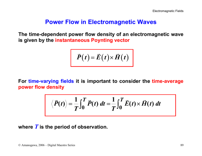
The time-dependent power flow density of an electromagnetic wave
is given by the instantaneous Poynting vector
G
G
G
P(t) = E(t)× H (t)
For time-varying fields it is important to consider the time-average
power flow density
G
G
1 TG
1 TG
P( t ) = ∫ P( t ) dt = ∫ E( t ) × H ( t ) dt
T 0
T 0
where T is the period of observation.
© Amanogawa, 2006 – Digital Maestro Series
89
Electromagnetic Fields
Consider time-harmonic fields represented in terms of their phasors
G
G
G
G
E( t ) = Re { E exp( jω t )} = Re{E} cos ω t − Im{E} sin ω t
G
G
G
G
H ( t ) = Re { H exp( jω t )} = Re{H} cos ω t − Im{H} sin ω t
The time-dependent Poynting vector can be expressed as the sum
of the cross-products of the components
G
G
G
G
E( t ) × H ( t ) = Re{E} × Re{H} cos2 ωt
G
G
+ Im{E} × Im{H} sin 2 ωt
G
G
G
G
− ( Re{E} × Im{H} + Im{E} × Re{H} ) cos ωt sin ωt
(Note that:
cos ωt sin ωt = 1 sin 2ωt )
2
© Amanogawa, 2006 – Digital Maestro Series
90
Electromagnetic Fields
The time-average power flow density can be obtained by integrating
the previous result over a period of oscillation T . The pre-factors
containing field phasors do not depend on time, therefore we have
to solve for the following integrals:
T
1 T
1 t sin 2ωt
1
2
=
cos ωt dt = +
∫
T 0
T 2
4ω 0 2
T
1 T 2
1 t sin 2ωt
1
=
sin ωt dt = −
∫
T 0
T 2
4ω 0 2
T
1 T
1 sin ωt
=0
cos ωt ⋅ sin ωt dt =
∫
T 0
T 2ω
2
0
© Amanogawa, 2006 – Digital Maestro Series
91
Electromagnetic Fields
The final result for the time-average power flow density is given by
G
G
1 TG
P( t ) = ∫ E( t ) × H ( t ) dt
T 0
G
G
G
G
1
= ( Re{E} × Re{H} + Im{E} × Im{H} )
2
Now, consider the following cross product of phasor vectors
G G*
G
G
G
G
E × H = Re{E} × Re{H} + Im{E} × Im{H}
G
G
G
G
+ j ( Im{E} × Re{H} − Re{E} × Im{H} )
© Amanogawa, 2006 – Digital Maestro Series
92
Electromagnetic Fields
By combining the previous results, one can obtain the following
time average rule
{
G
G
G G*
1 TG
1
P( t ) = ∫ E( t ) × H ( t ) dt = Re E × H
2
T 0
}
We also call complex Poynting vector the quantity
G 1 G G*
P = E× H
2
NOTE: the complex Poynting vector is not the phasor of the timedependent power nor that of the time-average power density!
G
G
P( t ) = Re {P}
G
G
( don't try P( t ) = Re {P exp( jωt )} )
Phasor notation cannot be applied to the product of two timeharmonic functions (e.g., P( t )), even if they have same frequency.
© Amanogawa, 2006 – Digital Maestro Series
93
Electromagnetic Fields
Consider a 1-D electro-magnetic wave moving along the z-direction,
with a specified electric field amplitude Eo
E x ( z) = Eo exp(−αz) exp(− jβz)
Eo
H y ( z) =
exp(−αz) exp(− jβz) exp(− jτ )
η
The time-average power flow density is
*
G
G G*
1
1
E
−αz − jβ z o −α z jβ z jτ
P( t ) = Re E × H = Re Eo e e
e e e
2
2
η
{
}
−2 α z
−2 α z
1
1
e
2e
2
= Eo
Re e jτ = Eo
cos τ
η
η
2
2
{ }
Power in a lossy medium decays as exp(-2α
© Amanogawa, 2006 – Digital Maestro Series
z)!
94
Electromagnetic Fields
Consider the same wave, with a specified amplitude for the
magnetic field
H y ( z) = Ho exp(−αz) exp(− jβz)
E x ( z) = η Ho exp(−αz) exp(− jβz) exp( jτ )
The time-average power flow density is expressed as
{
G
1
P( t ) = Re η Ho e−αz e− jβ z Ho* e−αz e jβ z e jτ
2
1
2 −2 α z
= η Ho e
cos τ
2
}
If α is the attenuation constant for the electromagnetic fields
⇒ 2α is the attenuation constant for power flow.
© Amanogawa, 2006 – Digital Maestro Series
95
Electromagnetic Fields
If the wave is generated by an infinitesimally thin sheet of uniform
current Jso (embedded in an infinite material with conductivity σ)
we have for propagation along the positive z-direction (normal to
the plane of the current sheet):I
Jso
Jso
Ho =
Eo = η
2
2
2
G
Jso
η e−2αz cos τ
P( t ) =
8
For this ideal case, an identical wave exists, propagating along the
negative z-direction and carrying the same amount of power.
© Amanogawa, 2006 – Digital Maestro Series
96
Electromagnetic Fields
Poynting Theorem
Consider the divergence of the time-dependent power flow density
G
G
G
G
G
G
G
∇ ⋅ P ( t ) = ∇ ⋅ ( E ( t ) × H ( t ) ) = H ( t ) ⋅ ∇ × E( t ) − E( t ) ⋅ ∇ × H ( t )
The curls can be expressed by using Maxwell’s equations
G
G
G
G
G
G
G
∂H
∂E
∇ ⋅ P( t ) = −µ H ( t ) ⋅
− σ E ( t ) ⋅ E( t ) − ε E ( t ) ⋅
∂t
∂t
∂ 1
∂ 1
2
2
= − σE ( t ) − ε E ( t ) − µ H 2 ( t )
∂t 2
∂t 2
Density of
dissipated
power
Rate of change
of stored electric
energy density
Rate of change
of stored magnetic
energy density
This is the differential form of Poynting Theorem.
© Amanogawa, 2006 – Digital Maestro Series
97
Electromagnetic Fields
Now, integrate the divergence of the time-dependent power over a
specified volume V to obtain the integral form of Poynting theorem
G
G
∫ ∇ ⋅ P( t) dV = w
∫∫ P( t) ⋅ ds = Power Flux through S
V
S
= −∫
V
∂
σE ( t ) dV −
∂t
2
Power dissipated
in volume
© Amanogawa, 2006 – Digital Maestro Series
∫
V
1
∂
2
ε E ( t ) dV −
2
∂t
Rate of change
of electric energy
stored in volume
∫
V
1
µ H 2 ( t ) dV
2
Rate of change
of magnetic energy
stored in volume
98
Electromagnetic Fields
Typical applications
G
Pin ( t )
α=?
G
Pout ( t )
1 m2
L
G
G
Pout ( t ) = Pin ( t ) exp(−2αL)
G
1 Pout ( t )
⇒α=−
ln G
2 L Pin ( t )
© Amanogawa, 2006 – Digital Maestro Series
Watts
2
m
Nepers
m
99
Electromagnetic Fields
Example:
G
Watts G
Watts
Pin ( t ) = 30
; Pout ( t ) = 5
; L = 20 m
2
2
m
m
Nepers
⇒ α = 0.0448
m
Pay attention to the logarithms:
G
Pout ( t )
ln G
= − ln
Pin ( t )
© Amanogawa, 2006 – Digital Maestro Series
G
Pin ( t )
G
Pout ( t )
100
Electromagnetic Fields
SURFACE A
∫∫
SURFACE B
G
Pin ( t ) = Power IN
∫∫
A
G
Pout ( t ) = Power OUT
B
Power dissipated
between A and B?
L
Area = Area(A) = Area(B)
G
G
Power IN = ∫∫ P ( t ) A dS = P( t ) A ⋅ Area
A
Power OUT =
∫∫
G
G
P ( t ) B dS = P( t ) B ⋅ Area
B
G
G
P( t ) B = P( t ) A exp( −2 αL)
Power dissipated = Power IN − Power OUT
© Amanogawa, 2006 – Digital Maestro Series
101
Electromagnetic Fields
Example
2
Area = 5 m ;
L = 1.0 cm;
f = 1.0 GHz; Eo = 10 V/m
ε = ε o ; µ = µ o ; σ = 0.45755 S/m
σ
⇒
= 8.2244637 General Lossy medium
ωε
η = 130.88∠ 0.725rad = 130.88∠ 41.534D
G
α = 40.0 Ne/m;
Pin ( t ) = 0.286 W/m2 ;
G
G
Pout ( t ) B = Pin ( t ) A exp(−2α L) = 0.12845 W/m2 ;
G
Power IN = Area ⋅ Pin ( t ) = 1.43 W
G
Power OUT = Area ⋅ P ( t ) B = 0.6423 W
Power dissipated = Power IN − Power OUT = 0.7876 W
© Amanogawa, 2006 – Digital Maestro Series
102

