lab handout - Missouri University of Science and Technology
advertisement
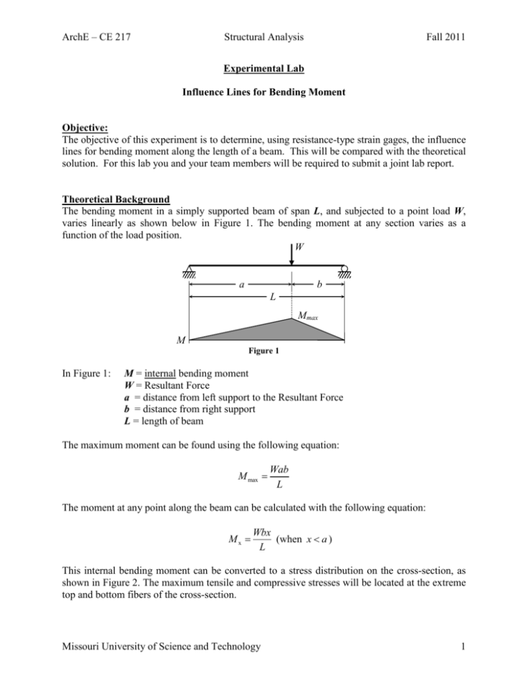
ArchE – CE 217 Structural Analysis Fall 2011 Experimental Lab Influence Lines for Bending Moment Objective: The objective of this experiment is to determine, using resistance-type strain gages, the influence lines for bending moment along the length of a beam. This will be compared with the theoretical solution. For this lab you and your team members will be required to submit a joint lab report. Theoretical Background The bending moment in a simply supported beam of span L, and subjected to a point load W, varies linearly as shown below in Figure 1. The bending moment at any section varies as a function of the load position. W a b L Mmax M Figure 1 In Figure 1: M = internal bending moment W = Resultant Force a = distance from left support to the Resultant Force b = distance from right support L = length of beam The maximum moment can be found using the following equation: M max Wab L The moment at any point along the beam can be calculated with the following equation: Mx Wbx (when x a ) L This internal bending moment can be converted to a stress distribution on the cross-section, as shown in Figure 2. The maximum tensile and compressive stresses will be located at the extreme top and bottom fibers of the cross-section. Missouri University of Science and Technology 1 ArchE – CE 217 Structural Analysis h c Fall 2011 N.A. σ b ε Figure 2 where b = width of the beam cross-section h = depth of the beam cross-section I = moment of inertia of the beam = bh3 12 h 2 For a U-Channel like the one used in this lab the parallel axis theorem will have to be used. Here is an example using a flanged beam. c = the distance from the neutral axis to the point in question = y Figure 2 The first step is to find y or the centroid of the shape. This is found by using the following equation: yA y A Make sure you keep track of what axis you are measuring each section’s centroid from, either the top or the bottom axis. To find the moment of inertia you solve for the moment of inertia of each section and then use the parallel axis theorem which is: I I c bh (d y )2 Missouri University of Science and Technology 2 ArchE – CE 217 Structural Analysis Fall 2011 where Ic = calculated moment of Inertia for each section d = the centroid for the section y = the centroid for the entire object The axial stress, σ, in the extreme top and bottom fibers of a rectangular cross-section is given by the following equation: Mc I Thus, the stress in the extreme fiber of the beam is: Mc M y M y I I I The strain in the beam, , is related to stress by: E Therefore, the strain in the extreme fiber of the beam is given by Equation (1): E My EI (1) The influence line of the bending moment at a section represents the moment at the section when a load W, which equals a unit value, moves along the beam. The influence line at a section could therefore be evaluated experimentally by: a) Measuring the strain at the extreme fiber of the section for a given position of the load W using electrical resistance strain gages. b) Evaluating the corresponding bending moment at the section using equation (1) for the c) beam with a given E. Repeating steps a) and b) when load W is acting at mid-span and quarter-span. **Note that: The position of W can be calculated through the following approach: W F1 F2 F3 c F2b F3 (a b) W (2) (3) Missouri University of Science and Technology 3 ArchE – CE 217 Structural Analysis F3 Fall 2011 F1 F2 a b c W Figure 3 Lab Instructions 1. Measure the dimensions of the beam: L, h, hf, be, and, bw and calculate y and I. Record the dimensions on the appropriate charts. The beam material is Aluminum with a Young’s modulus that equals 10600 ksi. The simplysupported beam with the corresponding position of the strain gage is shown in Figure (3). Loading Positions Strain Gage L/2 L/2 x Figure 4 Missouri University of Science and Technology 4 ArchE – CE 217 Structural Analysis Fall 2011 bw=0.25" H=0.25" hf=0.125" be=5" Figure 5 2. Record the strain gage location, x. 3. Record the initial reading of the strain gage. 4. Load the semi-truck with the assigned load and weigh each wheel set in order to find the individual forces. (This can be used later to find the resultant force) 5. Move the truck across the bridge and start the stopwatch as soon as the truck drives onto the beam. (Try to keep a constant speed.) 6. Using the data recorded develop a strain vs. position graph. ( You will need the time to estimate the speed of the truck and locate the positions). 7. Using the strain vs. position graph compute the largest bending moment and record its location. Missouri University of Science and Technology 5 ArchE – CE 217 Structural Analysis Fall 2011 Lab Report Write-up Requirements: Item 1. Show all Measured Values and Required Calculations. This includes measured bar properties, calculated moment of inertia (I), calculated section modulus (S); measured strain values, and calculated experimental bending moment versus positions of the truck (two positions: W at quarter-span; W at mid-span) Item 2. Plot the experimental influence line for the bending moment at the strain gage location using the data evaluated in item (1). Item 3. Plot the analytical influence lines at the strain gage location using the theory discussed in class. Compare the analytical influence lines with the experimental influence lines determined in item (2). **Note: Unit loads were not used in the experiment. The theoretical influence line values must be scaled to compare with the analytical results. Item 4. Discuss possible variables in your experimental tests which could affect your measured error between experiment and theory. Lab Report is due in 2 lab periods after you perform the lab. Questions: Chenglin Wu cwmqc@mst.edu Office at ERL 206 Office Phone: 573-341-6428 Missouri University of Science and Technology 6 Data Sheet – Influence Lines Dimensions Simply Supported L Length (in) h Cross-Section Height (in) 0.25 hf Base Thickness (in) 0.125 be Cross-Section Width (in) bw Leg Thickness (in) y Distance to Centroid (in) E Young’s modulus (ksi) I Moment of Inertia (in4) Wheel Set Weight (g) 5 0.25 10,600 Distance From Rear Wheel Set 1 2 3 Resultant Force 0


