Pendulum - Northern Illinois University
advertisement
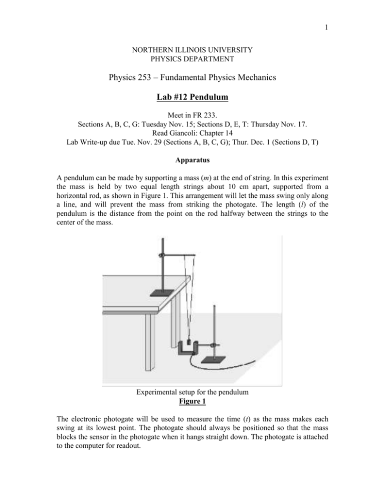
1 NORTHERN ILLINOIS UNIVERSITY PHYSICS DEPARTMENT Physics 253 – Fundamental Physics Mechanics Lab #12 Pendulum Meet in FR 233. Sections A, B, C, G: Tuesday Nov. 15; Sections D, E, T: Thursday Nov. 17. Read Giancoli: Chapter 14 Lab Write-up due Tue. Nov. 29 (Sections A, B, C, G); Thur. Dec. 1 (Sections D, T) Apparatus A pendulum can be made by supporting a mass (m) at the end of string. In this experiment the mass is held by two equal length strings about 10 cm apart, supported from a horizontal rod, as shown in Figure 1. This arrangement will let the mass swing only along a line, and will prevent the mass from striking the photogate. The length (l) of the pendulum is the distance from the point on the rod halfway between the strings to the center of the mass. Experimental setup for the pendulum Figure 1 The electronic photogate will be used to measure the time (t) as the mass makes each swing at its lowest point. The photogate should always be positioned so that the mass blocks the sensor in the photogate when it hangs straight down. The photogate is attached to the computer for readout. 2 Theory A pendulum mass (m) at the end of string is subject to two forces: gravity (Fg) and tension in the string (FT). Since the string doesn’t change length (or at least only by a very tiny amount that we shall ignore), Newton’s first law, the law of inertia, says that there is no net force on the string from end to end. If the string hangs vertically this means that FT = Fg = mg. When the pendulum mass is displaced from the vertical at an angle θ, there is no acceleration along the string; the only acceleration is perpendicular to the string (this is where the assumption that the string does not stretch comes in). In this case the tension in the string is equal to the component of the gravitational force along the string, which is FT = mg cosθ. The other component of the gravitational force results in a net force, Fnet = mg sinθ. From Newton’s second law, that net force causes an acceleration which is perpendicular to the string. The maximum position displacement (x) from the vertical is related to the angle and the length (l) of the string via (1) x lsin . For small angles the sine of the angle is approximately equal to the angle when the angle is measured in radians. Radians measure the number of radii around the circumference of a circle, so 360º = 2π radians, or 1 radian = 57.3º. As the pendulum passes through the vertical position and begins to rise on the other side, the net force acts to slow the mass down and eventually cause it to reverse direction. The force alternates back and forth, and the mass moves back and forth at a regular rate. The time it takes for the mass to go back and forth in one complete cycle is called the period (T). Note that the mass will travel through the vertical position twice during each period. If the maximum angle of amplitude isn’t too large the period can be approximated by l T 2 . (2) g Squaring both sides gives 4 2 2 T l. (3) g If the period squared is plotted versus the length, the line should pass through the origin and the slope of the line should be s 4 2 /g . The acceleration due to gravity is then related to that slope by 4 2 g . s Data Collection (1) Set the strings supporting the pendulum mass to at least 100 cm in length, and place a 100 g mass on the hanger. Measure and record the length (l) and record the mass (m) (remember to include the mass of the hanger). 3 (2) Open Logger Pro 3.7 on the computer. From the File pull down menu, select Open, then select the Physics with Vernier folder and open the file “14 Pendulum Periods”. When the Sensor Confirmation box appears, the Interface and Channel: selection should be set to ‘DIG1 on LabPro:1’, and the Sensor: selection should be set to ‘Photogate’. Then press the Connect button and a table with column headings ‘Time (s)’, ‘GateState’, and ‘Period (s)’ should appear on the left side of the screen, and a graph titled “Pendulum Periods” should appear on the right side of the screen. (3) Press COLLECT to initiate the photogate for data collection. (4) Pull the mass out about 10° from the vertical and release. (For a pendulum that is 100 cm long, that corresponds to pulling the mass about 15 cm to the side.) Be sure to pull the mass straight from the vertical position so the mass does not strike the photogate when released. (5) After the computer display indicates that the pendulum has passed back and forth five times and five periods have been recorded, press STOP to end data collection. (6) Calculate the average period from the five trials. (7) After recording the data from step 6, click on the Experiment drop down menu and select Clear Latest Run to reset the data logger to collect a new set of data. (8) Repeat steps 3 through 7 for a 200 g and 300 g mass. Record the mass and period in a table along with the first measurement with the 100 g mass. (9) Place the 200 g mass on the string. Repeat steps 3 through 7 for amplitudes of 15°, 20°, 25° and 30°. Use EQ 1 to determine the amount of displacement needed to achieve the desired angle. Record the angle, displacement and period in a table along with the 200 g measurement made at 10° in step 8. (10) Use the 200 g mass and an amplitude of 10°, and repeat steps 3 through 7 for pendulum lengths of 90 cm, 80 cm, 70 cm, 60 cm and 50 cm. Record the length, displacement and period in a table. Remember to measure the pendulum length from the horizontal rod to the middle of the mass, and to recalculate the displacement for each length using Eq. 1. Analysis (11) Use the data in the table from step 8, and plot the period T vs. mass m. Scale each axis from the origin, (0,0). (12) Use the data in the table from step 9, and plot the period T vs. amplitude angle θ. (13) Use the data in the table from step 10, and plot the period T vs. length l. (14) Use the data in the table from step 10, and plot the period T vs. length squared, l2. 4 (15) Use the data in the table from step 10, and plot the period squared, T2, vs. length l. (16) Find the slope of the line in the graph in step 15. Estimate the acceleration of gravity Lab Write-up In your lab write-up you will have to answer the following questions while discussing your experimental results: How consistently can you release the mass at the correct displacement? How would you improve this step of the experiment? Based on the graph in step 1, does the period appear to depend (appreciably) on mass? Do you feel that you have enough data to answer this question conclusively? According to your data and graph in step 12, does the period depend (appreciably) on amplitude? Explain. Based on the graph in step 13, does the period appear to depend (appreciably) on length? Explain. By comparing graphs in steps 13, 14 and 15, can you conclude that a directly proportional relationship exists between the plotted variables? Note that a straight line plot going through the graph's origin (0,0) is necessary for a direct proportion. How well does your value of g (step 16) agree with the accepted value, 9.8 m/s2? Give a percent error as part of the observation.
