electric power
advertisement

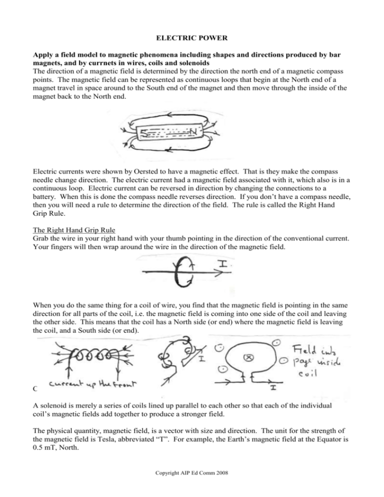
ELECTRIC POWER Apply a field model to magnetic phenomena including shapes and directions produced by bar magnets, and by currnets in wires, coils and solenoids The direction of a magnetic field is determined by the direction the north end of a magnetic compass points. The magnetic field can be represented as continuous loops that begin at the North end of a magnet travel in space around to the South end of the magnet and then move through the inside of the magnet back to the North end. Electric currents were shown by Oersted to have a magnetic effect. That is they make the compass needle change direction. The electric current had a magnetic field associated with it, which also is in a continuous loop. Electric current can be reversed in direction by changing the connections to a battery. When this is done the compass needle reverses direction. If you don’t have a compass needle, then you will need a rule to determine the direction of the field. The rule is called the Right Hand Grip Rule. The Right Hand Grip Rule Grab the wire in your right hand with your thumb pointing in the direction of the conventional current. Your fingers will then wrap around the wire in the direction of the magnetic field. When you do the same thing for a coil of wire, you find that the magnetic field is pointing in the same direction for all parts of the coil, i.e. the magnetic field is coming into one side of the coil and leaving the other side. This means that the coil has a North side (or end) where the magnetic field is leaving the coil, and a South side (or end). Circle with a dot means coming out of page. Circle with a cross means going into the page. A solenoid is merely a series of coils lined up parallel to each other so that each of the individual coil’s magnetic fields add together to produce a stronger field. The physical quantity, magnetic field, is a vector with size and direction. The unit for the strength of the magnetic field is Tesla, abbreviated “T”. For example, the Earth’s magnetic field at the Equator is 0.5 mT, North. Copyright AIP Ed Comm 2008 Quantify magnetic forces on current current carrying wires using F = IlB where the directions of I and B are either perpendicular to, or parallel to, each other. When a wire carrying a current is placed in a magnetic field it experiences a force. What determines the size of this force? Logic would tell you that the stronger the magnetic field or the larger the current in the wire, the bigger the force. The other factor that determines the size of the force is the length of wire actually in the magnetic field. All these combine to give the equation for :the Force, F, on a Current-carrying wire: F = BIl, where B is the symbol for the magnetic field, I for current and l for the length of wire. For the Force to be in Newtons, the Magnetic Field must be in Tesla, the Current in Amps and the Length of wire in Metres. In general, the Force, F, on a Current-carrying wire: F = nBIl, where n = number of coils. In this phenomenon, we have a vector, the magnetic field, acting on another vector, the current, to produce a third vector, the force. What direction does the force act on the wire? Once again, a rule has been devised to remember how to determine the force’s direction. In fact there are two different ways of remembering the rule. Teachers will have their preferences depending on their own schooling. The two versions are: Left Hand Rule Index (or pointing) finger, pointing ahead Second (or longest) finger, at right angles to the index finger Thumb, upright at right angles to both fingers Magnetic field Conventional Current Force Lock the three fingers in place so that they are all at right angles to each other. Now rotate your hand at the wrist so that the field and current line up with the directions in your problem. The thumb will now point in the direction of the force. Right Hand Slap Rule Fingers (out straight) Thumb (out to the side of the hand) Palm of hand Magnetic field Conventional Current Force Hold the hand flat with the fingers outstretched and the thumb out to the side, right angles to the fingers. Now rotate your hand so that the field and current line up with the direction in your problem. The palm of your hand now gives the direction of the force, hence the name. What happens if the wire is not at right angles to the magnetic field? Copyright AIP Ed Comm 2008 In general, the length of the wire is really the length of the wire “as seen” by the magnetic field, i.e. the component of the wire cutting across the wire. If the wire is at right angles to the field, cutting across the magnetic field, then the force is the maximum, F = BIl. If the wire and the current are running parallel to the field, then the force is zero. As the angle with the field increases from zero to 90 degrees, the force increases from zero to its maximum value. This implies a sine function as a correction factor for a general equation, but this is not required. Describe the operation of simple DC motors The magnetic force on a current makes the wire move, but the force acts only so long as the wire is in the magnetic field. To get continuous movement, the wire can be bent into a loop, put on a spindle that is free to spin and placed in the magnetic field. In this case the magnetic force is producing a turning effect on the wire and causing it to begin spinning. This turning effect is at a maximum when the line of action of the force is at its maximum distance from the spindle or axis of rotation. The turning effect will be zero when the line of action passes through the axis itself. F I S N F For a current-carrying coil in a magnetic field, the forces on the opposite sides of the coil are in opposite directions, because the current is travelling around the coil. The current and field are the same value, so the net force on the coil is zero. But, if the lines of action of the two forces are separate, then they will produce a turning effect on the coil. Let’s now look at a coil in a magnetic field and see how the forces and their turning effect vary for different positions of the coil in the magnetic field. When the coil is flat and parallel to the field, the separation of the forces is a maximum and the turning effect is a maximum and the coil begins to rotate. F F S N S N F F At an angle of 45 degrees, the forces are stiil the same size and in the same direction. The separation of the forces is less, and so is the turning effect. When the coil is at right angles to the field, the forces are not only pulling in the opposite direction, but along the same line, so the net force is still zero, but the turning effect is now zero. Copyright AIP Ed Comm 2008 If the coil has been rotating, its momentum will carry it through the perpendicular position. F S N F In this position there is a turning effect, but it is opposing the rotation and brings the coil back to the perpendicular position. The coil will now permanently stay in this position unless there is a change in the design. Design Options A meter The turning effect is proportional to the current. A helical or watch spring can be attached to the coil to oppose the magnetic force, and a needle attached to the coil. The larger the current, the larger the magnetic force, the more the spring is unbent, the larger the needle deflection. A motor To continue the rotation, the turning effect needs to be reversed each half turn. This is achieved be reversing the direction of the current in the coil with a commutator. F S N F It is most important that the turning effect and current are reversed when the coil is at right angles to the field, when the turning effect is momentarily zero. The current reverses twice in each turn. Apply a field model to define magnetic flux, , using = BA and the qualitative effect of differing angles between the coil and the field A current in a wire in a magnetic field can result in a force and hence movement of the wire. Can a moving wire in a magnetic field produce a current? Yes. This is called Electromagnetic Induction. The movement of a magnet in and out of a coil or solenoid easily demonstrates the generation of a current, which requires a voltage. Simple experiments indicate that: the size of the current or voltage is to the speed at which the magnet is moved, the direction of the current is reversed if the action of the magnet is reversed, there is no current or voltage when there is no relative movement between the magnet and coil. Similar results are found when the magnet is replaced by an electromagnet, that is a coil with a DC current passing through it. How can this phenomenon be explained? and how can the size of the induced voltage be determined? Copyright AIP Ed Comm 2008 One explanation uses the ideas from the previous section on magnetic forces. Another introduces a new concept called “Magnetic flux”. Using Magnetic Force on A Current or Charge Imagine a metal rod, not connected to anything, being pulled across a magnetic field. The moving positive and negative charges in the rod each constitutes a current and will experience a magnetic force. What will be the direction of the force on the positive and negative charges? F vel F The forces are in opposite directions. This will give the top of the rod a negative voltage, and the bottom a positive voltage. If the top and bottom of the rod are connected by a wire outside the magnetic field, then the negatively charged electrons will move from the top of the rod through the wire to the bottom of the rod. The magnetic force, due to the moving rod, will then take them to the top of the rod, giving them the energy to go around the circuit again. The “moving rod in the magnetic field” is a source of electrical energy like a battery. F vel Conventional current F Once a current is established, the magnetic field will act on it. The direction of this force will be to the left, slowing down the rod. To maintain the rod’s velocity, and the flow of current, a constant push to the right is needed. This is the source of energy that supplies the electrical energy. The force on the current must be to the left because if it was to the right, the rod would accelerate, producing a larger voltage, and a larger current, which produces a larger force, which produces a greater acceleration, ..... In this case energy is being created from nothing. So, from energy conservation principle alone, the magnetic force of the current must be to the left. Copyright AIP Ed Comm 2008 Using Magnetic Flux Magnetic Flux is defined as the amount of magnetic field passing through the area of a coil. The stronger the field, the more flux; the larger the area, the more flux. This leads to the formula B . A where the units of are weber. Explain the generation of voltage, including AC voltage, in terms of the rate of change of magnetic flux,(Faraday’s Law), the direction of the induced current (Lenz’s Law), and number of loops through which the flux passes, including calculations using induced = -/t Faraday used the idea of magnetic flux to explain the observation of the generation of electricity described at the beginning of this section. He summarised some of the observations with the statement:“The magnitude, or size, of the induced emf, or voltage, is proportional to the rate of change of magnetic flux” t Lenz extended Faraday’s explanation to include the direction of the induced emf. He stated:“The direction of the magnetic flux of the induced current was such that it opposed the change in flux of the applied magnetic field.” This is incorporated as a “minus” sign. , where N is the number of coils. t Note the “minus” sign does not mean a negative voltage. N Describe the production of voltage in generators and AC voltage in alternators, including the use of commutators and slip rings; The magnetic flux through a rotating coil in a magnetic field follows a sine curve with the maximum flux when the coil is at right angles to the coil. The magnetic flux is changing most rapidly when the coil is parallel to the field. In this case the flux is changing from going through one side to going through the opposite side. Given that the graph of magnetic flux with time is a sine curve, the graph of the induced emf will also be a sinusoidal curve, but 90 degrees out of phase, that is, the voltage produced is AC. Copyright AIP Ed Comm 2008 If the ends of the coil are connected to slip rings, the generated voltage will be AC. If the ends of the coil are connected to a commutator, the generated voltage will be a varying DC voltage. Compare sinusoidal AC voltages produced as a result of the uniform rotation of a loop in a constant magnetic flux in terms of frequency, period, amplitude, peak-to-peak voltage (Vp-p) and peak-to-peak current (Ip-p); The frequency of the AC voltage will be the same as the frequency of the turning coil. The frequency, which is the number of cycles in one second, of 240VAC, is 50 Hz. This is set by the generators in the power stations. The period is the time for one complete cycle and is equal to 0.02 seconds. The amplitude of AC voltage, or the peak voltage, is the maximum value of the voltage. The peak value of the AC voltage is proportional to the size of the magnetic field, B the area of the coils, A the number of coils, N the frequency or how quickly the flux changes. The peak to peak voltage, written as V p p , is equal to twice the peak voltage. Use rms values for a sinusoidal AC voltage, VRMS = Vpeak /√2 and IRMS = Ipeak /√2, and interpret rms in terms of the DC supply that delivers the same power as the AC supply; AC, or Alternating Current, voltage varies as a sine wave. The domestic AC voltage supplied by the SEC is described at 240 V AC. The 240 volts specifies the RMS or root mean square value, which is a way of averaging a sine wave. The RMS value of an AC voltage indicates the DC voltage that would have the same heating effect, that is provide the same power. V Time (sec) 339 V This relationship is given by V peak 2 x V RMS = 339.4 volts The AC current also follows a sine wave. There are similar relationships for I p p , I peak , I RMS Compare and contrast DC motors, generators and alternators; DC motors use a source of DC voltage to produce rotation. Generators and alternators use a source of rotation to produce a voltage, either AC or Dc in the case of a generator, only AC in the case of an alternator. All three devices have a coil of wire rotation in a magnetic field. A DC motor must use a split ring commutator, an alternator must use slip rings, while a generator could used either depending on whether AC or DD voltage was the required output. Explain transformer action, modelled in terms of electromagnetic induction for an ideal transformer, qualitatively; and quantitatively using number of turns in primary and secondary coils, voltage and current; ( N1 V 1 I 2 for an ideal transformer) N 2 V 2 I1 One of the advantages of AC voltage and current is that it produces a constantly changing magnetic field. This property is used in the design of a transformer. A transformer is another example of an application of electromagnetic induction. Copyright AIP Ed Comm 2008 Imagine a soft iron core shaped as a square ring. Around two sides are coils of wire. If an AC voltage is applied to one of the coils, called the primary coil, an alternating magnetic field will be set up in the iron core. This alternating magnetic field will propagate through the iron core to the other coil, called the secondary coil. Here the alternating field will induce an alternating voltage in this coil. If the primary coil has many turns, a strong field will be set up in the iron core. At the secondary coil, this strong field will set up a high voltage in each turn of the coil. If the secondary coil has many turns, a large AC voltage will be across the terminals of the secondary coil. V N In summary p p , where Vp and Vs are the primary and secondary voltages, and Np and Ns are Vs Ns the number of turns in the primary and secondary coils. This relationship is true for an ideal transformer where there is no energy loss either in the coils, or in the iron core. If there is no energy loss, then the “Power In” to the Primary coil will equal the “Power Out” of the Secondary coil. This can be written as VP IP = VS IS Model mathematically power supplied as P = VI and transmission losses using voltage drop V = IR) and power loss (P= I2R); Transformers are essential for the transmission of electrical power. They enable the transforming of relatively low generating voltages of 11,000 volts up to considerably higher voltages of 500kV for which the energy or power loss is less. A typical power output from a power station would be 300 MW, i.e. 3.0 x 10⁸ watts. At this voltage of 500kV the current is 600 amps. This large current will flow down and back through long, very low resistance cables to Melbourne. Unfortunately, even though their resistance is low, the large current means that some energy or power is lost. The expression for power lost in a resistance is I2R. For a cable of total resistance both ways of resistance of 5.0 ohms, this gives power loss of 600 x 600 x 5.0 = 1.8MW, i.e. 0.6% of the power output. Whereas, if the same power were transmitted at 100kV, the current would be 5 times bigger at 3000 amps, and the power loss would be 25 times larger at 4.5 x 10⁷ watts or 15% of the power output which is a significant amount. The effect of the I squared term in the Power Loss expression is a significant factor. It is important to also be aware of the consequences on the voltage that is available at the other end of the cables. In the second case the voltage drop across the cables is 3000 amp x 5 ohms = 15 kV, leaving 85 kV. Whereas in the case of the higher step-up transformer, the voltage drop is 600 amp x 5 ohm = 3 kV, leaving 497 kV, a small difference. The voltage output from a transformer is shared across the two cables to the domestic supply, as well as the domestic supply itself. Explain the use of transformers in an electricity distribution system; In an electricity distribution system transformers are use to minmise power loss by steping up the voltage at the generating plant for transmission to population centres where it is then stepped down to use in homes and factories. Copyright AIP Ed Comm 2008


