PHYSICS 201 - La Salle University
advertisement
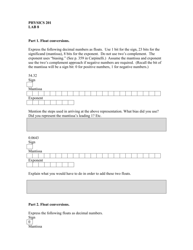
PHYSICS 201 LAB 8 Part 1. Float conversions. Express the following decimal numbers as floats. Use 1 bit for the sign, 23 bits for the significand (mantissa), 8 bits for the exponent. Do not use two’s complement. The exponent uses “biasing.” (See p. 359 in Carpinelli.) Assume the mantissa and exponent use the two’s complement approach if negative numbers are required. (Recall the bit of the mantissa will be a sign bit: 0 for positive numbers, 1 for negative numbers.) 54.32 Sign Mantissa Exponent Mention the steps used in arriving at the above representation. What bias did you use? Did you represent the mantissa’s leading 1? Etc. 0.0643 Sign Mantissa Exponent Explain what you would have to do in order to add these two floats. Part 2. Float conversions. Express the following floats as decimal numbers. Sign 0 Mantissa 1 1 0 1 1 0 1 1 0 Exponent 0 0 0 0 0 1 1 1 Sign 1 Mantissa 1 0 1 0 1 0 1 0 1 Exponent 1 1 1 0 0 1 1 1 0 0 0 0 0 0 0 1 0 0 0 0 0 0 0 1 0 1 0 1 0 1 0 1 0 1 0 1 Part 3. Multiplication Perform the following multiplication in detail. 1 1 1 0 0 1 1 1 1 1 0 0 0 1 1 0 Part 4. Digital to Analog Conversion. Build the following circuit. The digital to analog converter can be found under the MIXED button. A digital (eight-bit) number is entered in the top inputs. The output is an analog voltage that corresponds to a fraction of the maximum voltage. In particular, the fraction of the voltage is the fraction represented by the bits. This should remind you of the mantissa of a float. Fill in the table below. 7 6 5 4 3 2 1 0 1 1 0 0 0 1 1 0 1 0 1 0 1 0 0 1 0 1 1 0 0 1 1 0 1 0 0 0 0 1 1 0 0 0 1 0 1 0 0 1 0 1 1 0 0 1 1 0 Voltage % of Vmax . Part 5. Ring Counter: Special Case of Shift Register Even performing a simple instruction, such as loading a value into the accumulator, requires several steps. A ring counter can be used to keep track of these steps. In a clock analogy, if the program counter is the minute’s hand, the ring counter is the second’s hand. Build the circuit below. Describe its behavior when you put the switch low and when you put the switch high. Part 6. Recall we built in lab the parallel loading register shown below. Notice the part of the circuit surrounded by the thick rectangle; it serves to select whether the data entering the flip-flop comes from the data switch or from the output of the same flip-flop. That part of the circuit could be called a ____________. Rewire your parallel loading register to turn it into a parallel loading shift register. Have zeros fed in while the shifting occurs.
