(Phase II) Residual Waste Landfills and
advertisement

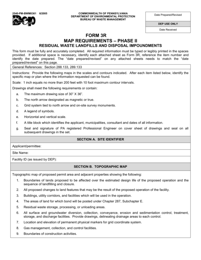
2540-PM-BWM0361 6/2005 COMMONWEALTH OF PENNSYLVANIA DEPARTMENT OF ENVIRONMENTAL PROTECTION BUREAU OF WASTE MANAGEMENT Date Prepared/Revised DEP USE ONLY Date Received FORM 3R MAP REQUIREMENTS – PHASE II RESIDUAL WASTE LANDFILLS AND DISPOSAL IMPOUNDMENTS This form must be fully and accurately completed. All required information must be typed or legibly printed in the spaces provided. If additional space is necessary, identify each attached sheet as Form 3R, reference the item number and identify the date prepared. The “date prepared/revised” on any attached sheets needs to match the “date prepared/revised” on this page. General References: Section 288.133, 289.133 Instructions: Provide the following maps in the scales and contours indicated. After each item listed below, identify the specific map or plan where the information requested can be found. Scale: 1 inch equals no more than 200 feet with 10 foot maximum contour intervaIs. Drawings shall meet the following requirements or contain: a. The maximum drawing size of 30” X 36”. b. The north arrow designated as magnetic or true. c. Grid system tied to north arrow and on-site survey monuments. d. A legend of symbols. e. Horizontal and vertical scale. f. A title block which identifies the applicant, municipalities, consultant and dates of all information. g. Seal and signature of PA registered Professional Engineer on cover sheet of drawings and seal on all subsequent drawings in the set. SECTION A. SITE IDENTIFIER Applicant/permittee: Site Name: Facility ID (as issued by DEP): SECTION B. TOPOGRAPHIC MAP Topographic map of proposed permit area and adjacent properties showing the following: 1. Boundaries of lands proposed to be affected over the estimated design life of the proposed operation and the sequence of landfilling and closure. 2. All proposed changes to land features that may be the result of the proposed operation of the facility. 3. Buildings, utility corridors, and facilities which will be used in the operation. 4. The areas of land for which bond will be posted under Chapter 287, Subchapter E. 5. Residual waste storage, processing, or unloading areas. 6. All surface and groundwater diversion, collection, conveyance, erosion and sedimentation control, treatment, storage, and discharge facilities. Provide drawings, delineating drainage areas to each control. 7. Location and elevation of permanent physical markers for grid coordinate system. 8. Gas management, collection, and control facilities. 9. Boundaries of construction activities. 2540-FM-BWM0361 6/2005 SECTION B. TOPOGRAPHIC MAP (Continued) 10. Barriers, fences, and similar structures. 11. Sedimentation ponds, stormwater impoundments, or similar facilities. 12. Access roads to site, including grades, dimensions, and profiles of roads. 13. Monitoring wells. 14. Area for isolating detected radioactive waste. 15. Location of radioactive monitoring equipment. 16. Location of meteorological equipment. SECTION C. GRID COORDINATE SYSTEM Grid coordinate system for proposed permit area. Horizontal control system shall consist of a grid not to exceed 200 feet square sections. Two permanent benchmarks are to be provided for horizontal and vertical control. Benchmarks are to be placed on the grid to allow instrument set up. SECTION D. PLANS, DESIGNS, CROSS-SECTIONS, AND MAPS Plans, Designs, Cross-Sections, and Maps Design Items to be included: a. Compaction of solid waste, thickness of lift. b. Application of daily cover material, intermediate, final cover. c. Elevation and grade of final cover. d. Management of surface water in accordance with Chapter 102. e. Erosion control in accordance with Chapter 102. f. Schedule of filling. g. Site preparations. h. Monitoring devices. i. Location and limits of areas previously filled, if applicable. j. Cross sections indicating the interface details between areas previously filled and areas to be filled, where applicable. k. Limits of construction defined by grid controls. l. Borrow areas on-site defined by grid controls/or off-site. m. Location of underground and surface mines on-site. (Indicate extent of mining activity) n. Cross sections shown on the plans shall be referenced to the grid system for horizontal location and permanent benchmark, whenever applicable. o. Grades required for proper drainage of lifts. p. The design plans shall include a cross section of the access roads and all weather roads (with associated drainage system) identifying construction materials, slopes, grades, and distances. q. Cross sections, grades and/or profiles of diversion ditches, capacities, and calculations for ditch volume. r. A construction schedule shall be submitted by the applicant to the Department in a format established by the Department. -2- 2540-FM-BWM0361 6/2005 SECTION D. PLANS, DESIGNS, CROSS-SECTIONS, AND MAPS (Continued) s. Gas Management - location of vents, flares, collection lines, recovery systems, design of system components. t. Layout of leachate collection, detection, and conveyance pipes. u. Liner system cross-section. v. Temporary erosion and sedimentation controls. w. Soil storage area locations. x. Location of collection and treatment facilities. y. Cross section of treatment lagoons and proposed collection facilities. z. Location of discharge points of treated leachate (requires industrial waste permit). aa. Cross sections of phases or cells. bb. Typical cross section showing components of landfill design. cc. Location of scales for weighing. dd. Cross-sections of on-site soil borrow areas. ee. Cross-sections of soil base for Class III landfills. ff. Area for isolating detected radioactive waste. gg. Location of radioactive monitoring equipment. hh. Location of meteorological equipment. -3-


