electricity - Carlingford High School
advertisement

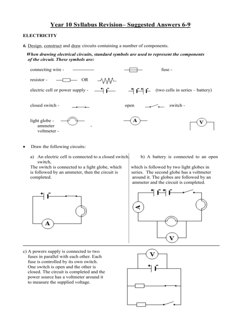
Year 10 Syllabus Revision– Suggested Answers 6-9 ELECTRICITY 6. Design, construct and draw circuits containing a number of components. When drawing electrical circuits, standard symbols are used to represent the components of the circuit. These symbols are: connecting wire resistor - fuse OR (two cells in series – battery) electric cell or power supply - closed switch - light globe ammeter voltmeter open switch - - Draw the following circuits: a) An electric cell is connected to a closed switch. b) A battery is connected to an open switch, The switch is connected to a light globe, which which is followed by two light globes in is followed by an ammeter, then the circuit is series. The second globe has a voltmeter completed. around it. The globes are followed by an ammeter and the circuit is completed. c) A powers supply is connected to two fuses in parallel with each other. Each fuse is controlled by its own switch. One switch is open and the other is closed. The circuit is completed and the power source has a voltmeter around it to measure the supplied voltage. 7. Describe voltage, resistance and current using analogies. Provide an outline of voltage, resistance and current using analogies. Voltage (V) – a measure of how much electrical energy is supplied to electrical particles (electrons) moving through the circuit. It is correctly known as potential difference because it measures a change in the potential (stored) energy of charge as it moves from one place to another or through an electrical component. It can also be thought of as the pushing force on charge. It is measured with a voltmeter and the standard unit it the volt (V). Resistance (R) – a measure of a substances’ opposition to the flow of electric charge. All substances have resistance, although some substances are more resistant than others. Substances with relatively low resistances are known as conductors while those with fairly high resistances are called insulators. The standard unit is the ohm (Ω) named after Georg Ohm. Current (I) – a measure of the amount of electric charge passing a particular point in a circuit every second. The direction of current flow in a circuit is defined as the direction a positive charge would move (+ to -). It is measured with an ammeter and the standard unit is the Ampere (A) named after Andre Ampere. (1 A = 6,000,000,000,000,000,000 electrons per second). (Even though we know today that electric current is the flow of negative particles, scientists many years ago believed it to be the flow of positive particles, however, the direction of current is still for a positive particle. This is known as Conventional Current.) The best analogy to use to describe these properties in relation to an electric circuit is to liken a circuit to a water pump, ie. Gauge to measure difference in pressure (voltmeter) Water flow Meter to measure rate of flow (ammeter) Tap Pump - The flow of water through the pipes is like the flow of electric charge in a circuit. The pump supplies the energy or pressure to force the water through the pipes like a power supply to the electric charges. The smaller section of pipes slows the flow of water and creates a pressure difference (high to low) like an electrical resistor. The tap controls flow like a switch. The gauge measures the pressure difference just like a voltmeter measures potential difference. - The meter measures the amount of water passing per unit time like an ammeter measures the flow of electric charges. 8. Describe qualitatively the relationship between voltage, resistance and current. Provide an outline of the relationship between voltage, resistance and current using descriptive explanations. The three variables voltage, resistance and current are all linked by a simple equation, ie. V = IR where: V = voltage (v) I = current (A) R = resistance (Ω) This equation forms the basis of a physical law known as Ohm’s Law, which states: “the current flowing through a conductor is proportional to the voltage difference between its ends”. Relating current to voltage and resistance shows that: a) Current is directly proportional to voltage (similar effect). b) Current is inversely proportional to resistance (opposite effect). This can be shown mathematically as follows: Say a voltage of 10V was applied to a resistor of 5Ω, then current flow would be: I= = V R I= V R I= V R 10 5 = 20 5 = 5 5 = 2A The current is 2A. Now suppose the voltage This time the voltage is was doubled while the halved while the resistance resistance was kept constant: is kept constant: = 4A The current is doubled. = 1A The current is halved. Similarly it can be shown that the current is inversely proportional to the resistance of a conductor, ie. Doubling the resistance halves the current and halving the resistance doubles the current. Say a voltage of 10V was applied to a resistor of 5Ω, then current flow would be: I= = Now suppose the resistance was doubled while the voltage was kept constant: This time the resistance is halved while the voltage is kept constant: V R I= V R I= 10 5 = 10 10 = = 2A The current is 2A. = 1A The current is halved. V R 10 2 .5 = 4A The current is doubled. 9. Compare advantages and disadvantages of series and parallel circuits Select appropriate and relevant characteristics and describe ways in which the advantages and disadvantages of series and parallel circuits are similar or different. A series circuit is one in which all of the components are connected in line so that there is only one pathway for the electric charges to flow. Eg. One pathway for electricity A parallel circuit is one in which all of the components are connected along separate pathways so that the electric charges have more than one-way they can go. Eg. Three pathways for electricity These two types of circuits have advantages and disadvantages, ie. (the table below relates to the two diagrams above with all globes being identical): SERIES CIRCUITS ADVANTAGES The same amount of current flows through all components. Less wires are needed to connect all the components. PARALLEL CIRCUITS ADVANTAGES If one component breaks the others will still (if one globe blows the others still glow). Each component gets the same voltage (energy) each glows with the same brightness. Each globe can be operated by itself. DISADVANTAGES If one component breaks the whole circuit is cut, thus if one globe blows none of them glow. Each component uses some of the total voltage (energy) thus the more globes added the dimmer they become. All components (globes) work at the same time. DISADVANTAGES Many more wires are needed to connect all the components. More current is needed each time a new component (globe) is added due to more pathways for the current to flow along.


