Introduction In this project, a 3D geological (static) model of a
advertisement
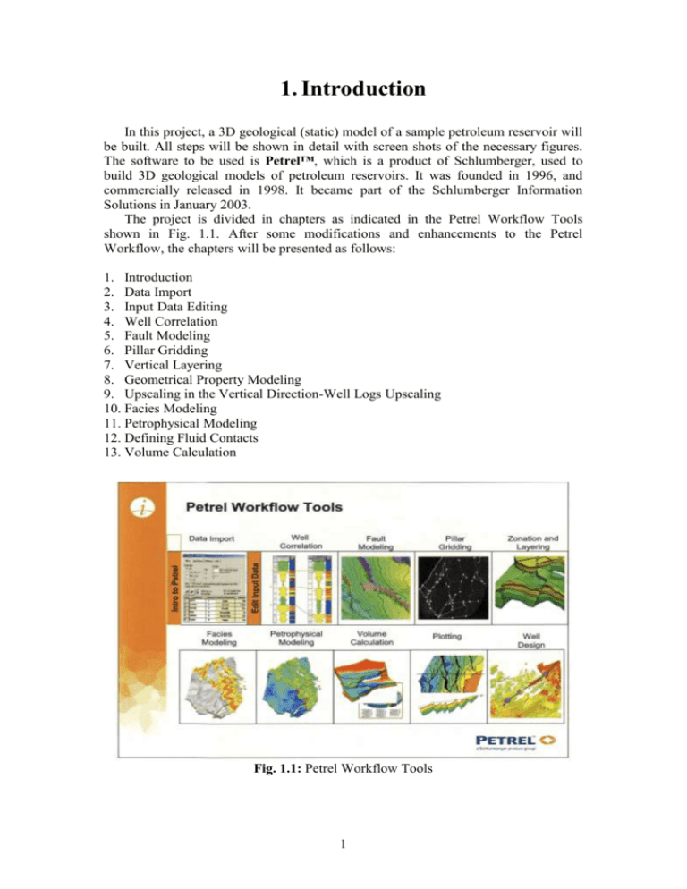
1. Introduction In this project, a 3D geological (static) model of a sample petroleum reservoir will be built. All steps will be shown in detail with screen shots of the necessary figures. The software to be used is Petrel™, which is a product of Schlumberger, used to build 3D geological models of petroleum reservoirs. It was founded in 1996, and commercially released in 1998. It became part of the Schlumberger Information Solutions in January 2003. The project is divided in chapters as indicated in the Petrel Workflow Tools shown in Fig. 1.1. After some modifications and enhancements to the Petrel Workflow, the chapters will be presented as follows: 1. Introduction 2. Data Import 3. Input Data Editing 4. Well Correlation 5. Fault Modeling 6. Pillar Gridding 7. Vertical Layering 8. Geometrical Property Modeling 9. Upscaling in the Vertical Direction-Well Logs Upscaling 10. Facies Modeling 11. Petrophysical Modeling 12. Defining Fluid Contacts 13. Volume Calculation Fig. 1.1: Petrel Workflow Tools 1 1.1 The Required Reservoir Data The following wells, along with their well headers (well location map), well deviations (well paths), well logs, and well tops (formation tops), are supplied: A10, A15, A16, B1, B2, B4, B8, B9, C1, C2, C3, C4, C5, C6, and C7. The stratigraphic succession of the reservoir under study is given in the following table: Succession 1 (top) 2 Horizon Cretaceous Tarbert 3 Ness 4 (bottom) Etive Zone Tarbert-3 Tarbert-2 Tarbert-1 Ness-2 Ness-1 The data that are given for each horizon includes: 3D seismic lines, fault polygons, fault sticks, and isochors. 1.2 Petrel User Interface When starting Petrel, it displays three main windows: the Display Window, the Project Explorer, and the Process Diagram as shown in Fig. 1.2. All windows are either docked or float. Double-clicking the window toggles its docking state. If the project explorer or the process diagram windows are not shown, they can be displayed from the View menu command using First Petrel Explorer and Second Petrel Explorer respectively. On the other hand, if a 3D window is not shown, it can be displayed using the Windows tab of the process diagram as shown in Fig. 1.2. 1.2.1 Display Window The display window is the parent window of Petrel (gray area). It forms the client area where a variety of windows, which are listed under the Windows menu command, can be hosted (displayed) in this area. Examples are 3D and 2D windows, well section windows (for well correlation), interpretation windows (for seismic interpretation), map/intersection windows (for plotting), etc. 1.2.2 Project Explorer This window contains all the data sorted in different tabs in the order they should be used. All data that are not linked to any 3D grid will be sorted under the Input tab. Examples are wells and well tops, interpreted lines, polygons, functions, well sections, 2D grids and more. All data linked to a 3D grid will be sorted, together with the 3D gird information system data, under the Models tab. Examples are the generated faults, gridded horizons, 3D properties, zones, etc. 2 1.2.3 Process Diagram This window contains a list of all available processes in Petrel. They are sorted in the order they should be used, and the first processes will have to be executed before you get access to other processes down the list. For example, you must create a 3D grid before you can insert horizons into it, and you must create zones before you can insert layers into them. Project Explorer Process Diagram Display Window Fig. 1.2: Petrel user interface 1.2.4 Toolbars The basic toolbars in Petrel are 1. File Actions 2. Edit Actions 3 3. 3D Buttons 4. 3D Tools 5. 3D Processes The File/Edit Actions toolbars are relevant to the Project Explorer and the Process Diagram windows. The other three toolbars are relevant to 3D Windows. When the File and Edit Actions toolbars are hidden, they can be displayed by selecting Show all relevant Toolbars from the View menu. The other toolbars are displayed by hiding and redisplaying 3D Windows. Double-clicking on a toolbar toggles its docking state. 1.2.5 Changing the Background Color of a 3D Window The color of a 3D window can be changed as follows: 1. Select Open Window Settings for Color/Name from the 3D Buttons toolbar as shown in the toolbar below (first icon to the left of the 3D Buttons toolbar). 2. A "Settings for '3D Window 1' " dialog box appears as shown in Fig. 1.3. Select the desired color from the Color drop-down combo box, and press the OK button. Fig. 1.3: Settings for '3D Window 1' 4 3. Select the “Toggle Background Color and Black” from the 3D Buttons toolbar as shown above (second icon to the left of the 3D Buttons toolbar). 1.3 Main Steps to Building a New Static Model When starting a new project, Petrel organizes the input data in the Input tab of the Project Explorer window. The following steps are required to build a 3D geological model of a petroleum reservoir, 1. 2. 3. 4. 5. 6. 7. 8. 9. 10. 11. Data Import Input Data Editing Well Correlation Fault Modeling Pillar Gridding Vertical Layering Geometrical Property Modeling Upscaling in the Vertical Direction-Well Logs Upscaling Facies Modeling Petrophysical Modeling Defining Fluid Contacts 1.4 Creating a New Project To start a new project, follow the steps: 1. Select New Project from the File menu. A Save warning of a previous project may appear. If no project is active, ignore the message and press No, 2. A new Display Window appears with black background color, 3. Select Save Project from the File menu, 4. When the Save Project As dialog box appears, specify the name and location of the project. Now you are ready to start the first step of building a 3D geological model, which is Data Import as explained in the next section. 5
