Information on STP
advertisement

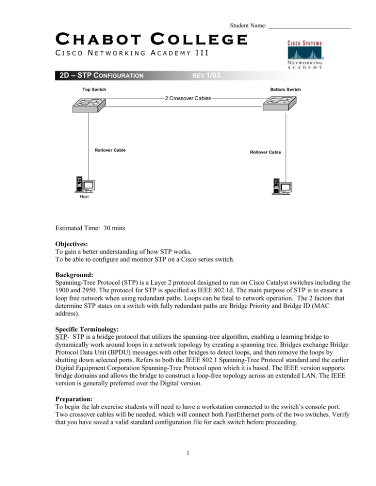
Student Name: ___________________________ CHABOT COLLEGE CISCO NETWORKING ACADEMY III 2D – STP CONFIGURATION REV 1/03 Top Switch Bottom Switch 2 Crossover Cables Rollover Cable Rollover Cable Host Estimated Time: 30 mins Objectives: To gain a better understanding of how STP works. To be able to configure and monitor STP on a Cisco series switch. Background: Spanning-Tree Protocol (STP) is a Layer 2 protocol designed to run on Cisco Catalyst switches including the 1900 and 2950. The protocol for STP is specified as IEEE 802.1d. The main purpose of STP is to ensure a loop free network when using redundant paths. Loops can be fatal to network operation. The 2 factors that determine STP states on a switch with fully redundant paths are Bridge Priority and Bridge ID (MAC address). Specific Terminology: STP- STP is a bridge protocol that utilizes the spanning-tree algorithm, enabling a learning bridge to dynamically work around loops in a network topology by creating a spanning tree. Bridges exchange Bridge Protocol Data Unit (BPDU) messages with other bridges to detect loops, and then remove the loops by shutting down selected ports. Refers to both the IEEE 802.1 Spanning-Tree Protocol standard and the earlier Digital Equipment Corporation Spanning-Tree Protocol upon which it is based. The IEEE version supports bridge domains and allows the bridge to construct a loop-free topology across an extended LAN. The IEEE version is generally preferred over the Digital version. Preparation: To begin the lab exercise students will need to have a workstation connected to the switch’s console port. Two crossover cables will be needed, which will connect both FastEthernet ports of the two switches. Verify that you have saved a valid standard configuration file for each switch before proceeding. 1 Student Name: ___________________________ Resources Required: In order to complete the lab students will require at least 2 switches, 1 workstation, and 2 Ethernet crossover cables. Websites Required: Lab from Cisco on STP http://www.cisco.com/warp/public/473/5.html - oper Information on STP http://www.cisco.com/univercd/cc/td/doc/product/lan/c2900xl/29_35sa6/eescg/masctrnk.htm. Notes: _______________________________________________________________________________________ _______________________________________________________________________________________ _______________________________________________________________________________________ _______________________________________________________________________________________ Procedure: Step 1: Begin by making sure that all cables are properly connected. Connect the two crossover cables as shown below. This configuration allows a full redundancy backbone between the switches. Example: 1900 2950 1900 Bx Ax 2950 Bx 24 Ax 23 24 23 Step 2: Once in Command Line Interface (CLI) mode on the 1900 Switch, delete all saved configurations by entering the following commands: Switch_1900#delete nvram To delete NVRAM on the 2950, Switch_2950#erase start After deleting both configurations unplug the 1900 switch power cord and then plug it back in, or reload the 2950. Step 3: 2 Student Name: ___________________________ After the switches have performed self test, you should notice that only the ports with cables attached to them are lit up. During the first minute after self test, what is the color of the LED lights above the last two FastEthernet ports on both switches? _________________ After the ports have entered into their STP states the LED lights turn either green or amber. You should notice that only 1 port out of the four turns amber. Why does one of the ports turn amber? What STP state is it in? (Hint: use the show spantree or show spanning-tree command if you need help.) ________________________________________________________ Why are 3 of the ports green? What STP state are they in? ________________________________________________________ Step 4: Enter the command line interface on the 1900 switch, or enter privileged mode on the 2950 switch. Enter a hostname and password on each switch, Switch1 for the top switch, Switch2 for the bottom. (Refer to your past lab assignments if you are unsure how to do this.) Step 5: Exit configuration mode by typing Ctrl+Z. Next enter the following command to view the port priority of FastEthernet ports 0/26 (Ax) and 0/27 (Bx) on the 1900, ports 23 and 24 on the 2950. Switch1#show spantree 1 (for the 2950 show spanning-tree vlan 1 or show spanning-tree brief) Continue to press the space bar until you are able to view the STP statistics for Port FastEthernet 0/26 and Port FastEthernet 0/27 (23 and 24 for the 2950). What is the port priority for FastEthernet port 0/26? And for 0/27 (23 and 24)? Switch1________________________________________________________ Switch2________________________________________________________ 3 Student Name: ___________________________ Step 6: Enter the following commands to view the MAC address of the switch. Switch1#show version What is Switch1’s MAC address? _____________________________ What is Switch2’s MAC address? _____________________________ Why do you think the MAC address of the switch is important for STP? ________________________________________________________ Step 7: Plug the console cable back into Switch 1 and enter into the CLI. Set the bridge priority to 1 by entering the following command in global configuration mode: Switch1(config)#spantree-template 1 priority 0 (2950 spanning-tree priority 0) This command sets Switch1 to the root bridge for the network. Now issue the following command to view the changes you have just made to the switch: Switch1#show spantree 1 You should notice that the bridge priority is now set to 0. (Do not confuse bridge priority with port priority.) Note: You can always tell which switch is the root switch by looking at the color of the STP ports, all of the root switch’s STP ports will always be green. Step 8: Notice that the port priority for all four ports that you documented was the same. What 2 factors are used to determine STP states for fully redundant paths? ____________________________________________________ 4 Student Name: ___________________________ Step 9: Enter Switch1’s interface configuration mode for FastEthernet port 0/27 (or 0/24) by entering the following command: Switch1#config t Switch1(config)#interface fa 0/27 (f0/24) Once in interface configuration mode enter the following commands to change the priority setting on the port. Switch1(config-if)#spantree priority 0 (spanning-tree port-priority 0) You should notice some of the lights on the switch changing to amber as they learn their new STP states. You’ll notice after a few minutes that the port whose priority you changed is now in forwarding mode (green light). Why did the STP port states change when you lowered the priority setting on the port? ________________________________________________ Step 10: Plug the console cable back into Switch 1 and enter into the CLI. Set the bridge priority to 65535 by entering the following command in global configuration mode: Switch1(config)#spantree-template 1 priority 65535 (2950 spanning-tree priority 65535) Now issue the following command to view the changes you have just made to the switch: Switch1#show spantree 1 (show spanning-tree brief) You should notice that the bridge priority is now set to 65535. By giving Switch1 a higher priority number you have changed the root switch to Switch2, which is still set at the lower (default) priority of 32768. You should notice the lights beginning to change above the ports. Step 11: The purpose of STP is to reduce the risk of loops in the network as well as provide redundant paths in case a route goes down. Unplug the FastEthernet port 0/24 on Switch2. You should notice after a few minutes that the amber colored port turns to green (forwarding mode). From this you can see that if a port goes down, STP automatically switches to forwarding mode on the blocked port, thereby providing full path redundancy. Step 12: Restore the standard configurations to the two switches. Comments: _______________________________________________________________________________________ _______________________________________________________________________________________ __________________________________________________________________________________ 5


