CHE331.Lab#2.fluoElect
advertisement
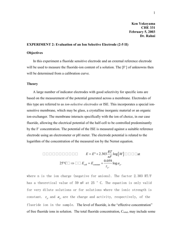
1 Ken Yokoyama CHE 331 February 5, 2003 Dr. Rahni EXPERIMENT 2: Evaluation of an Ion Selective Electrode (2-5 II) Objectives In this experiment a fluoride sensitive electrode and an external reference electrode will be used to measure the fluoride-ion content of a solution. The [F-] of unknowns then will be determined from a calibration curve. Theory A large number of indicator electrodes with good selectivity for specific ions are based on the measurement of the potential generated across a membrane. Electrodes of this type are referred to as ion-selective electrodes or ISE. This incorporates a special ionsensitive membrane, which may be glass, a crystalline inorganic material or an organic ion-exchanger. The membrane interacts specifically with the ion of choice, in our case fluoride, allowing the electrical potential of the half-cell to be controlled predominantly by the F- concentration. The potential of the ISE is measured against a suitable reference electrode using an electrometer or pH meter. The electrode potential is related to the logarithm of the concentration of the measured ion by the Nernst equation. RT log M nF 0.059 log aF zF E E 2.303 25°C Ecell Econstant at where n is the ion charge (negative for anions). The factor 2.303 RT/F has a theoretical value of 59 mV at 25 °C. The equation is only valid for very dilute solutions or for solutions where the ionic strength is constant. z F and aF are the charge and activity, respectively, of the fluoride ion in the sample. The level of fluoride, is the “effective concentration” of free fluoride ions in solution. The total fluoride concentration, Ctotal, may include some 2 bound or complexed ions as well as free ions. The electrode responds only to free ions, whose concentration is: Cfree = Ctotal - Cbound where Cbound is the concentration of fluoride ions in all bound or complex forms. The ISE responds to the activity of the free ion in solution. In order to calculate concentration from activity, the ionic strength of the solution must be known. This information is not usually available for unknown samples. Therefore, the usual practice is to treat both standards and samples with an ionic strength adjustor (ISA) to make the total ionic strength very high. The ionic strength is then constant for all solutions and becomes Ecell Econstant 0.059 log F zF When interfering species are a factor, the general equation is Ecell Econstant 0.059 log(ai Kij a nj z ) zF where K ij is the selectivity coefficient and ai and a j refer to the activity and charge, respectively, of the interfering ions. The selectivity coefficient is a measure of the extent of the interference posed by a particular ion that might be present in the sample. A small selectivity coefficient for a given ion indicates less interference from that ion. A calibration curve is prepared for the response of a particular electrochemical cell to a series of standard fluoride solutions. The measured potentials are plotted versus the logarithm of the concentrations or activities of the fluoride ion. The result is a straight line with a slope of 59.16 mV if a Nernstian response is obtained. In neutral solutions, fluoride concentration can be measured down to 10-6 M (0.02 ppm) fluoride. The upper limit of detection is a saturated fluoride solution. 3 Procedure A. Preparation of Solutions 1. Prepare each of the following fluoride solutions in 25 ml volumetric flasks by serial dilution of the 100 ppm fluoride standard, 50, 25, 15, 10, 5, and 1 ppm. 2. The unknowns are samples of sodium fluoride. B. Making the Measurement 1. Set the pH meter to read millivolts (mV). A glass beaker will be used for each fluoride measurements. 2. Place the reference and fluoride ISE into solution, allow the pH meter reading to stabilize, and record the voltage in millivolts (mV). 3. When measuring the voltage of the standard solutions, begin with the most dilute solution and measure the fluoride standards in order of increasing concentration. 4. Rinse the electrodes well with distilled water and blot dry between each measurement with kimwipes. C. Calculations 1. A calibration graph is obtained by plotting the cell potential in millivolts against the -log [F-]. Determine the fluoride ion concentration of your unknown from the calibration graph. Calculate the slope of the calibration curve over the linear region. The plot may deviate from the linearity at low fluoride concentrations. 2. By comparison of the potentials measured for the unknown and standards, estimate the concentration of your unknown. 4 DATA Analyte Standards DI water Tap water 0.01 M NaBr 0.01 M NaCl Unknown #1 (NaF) Unknown #2 (NaF) Unknown #3 (NaF) Instrument F- (ppm) A 100 B 100 A 50 B 50 A 25 B 25 A 15 B 15 A 10 B 10 A 5 B 5 A 1 B 1 A B A B A B A B A 15? B A 100? B A 100? B [F-] (Molarity) -logF0.0053 2.28 0.0053 2.28 0.0026 2.58 0.0026 2.58 0.00132 2.88 0.00132 2.88 0.00079 3.10 0.00079 3.10 0.00053 3.28 0.00053 3.28 0.00026 3.58 0.00026 3.58 0.000053 4.28 0.000053 4.28 4.89 4.68 5.28 5.28 0.000676 0.000387 0.00417 0.00179102 0.00427 0.001941 3.17 3.08 2.38 2.40 2.37 2.37 Potential (mv) 1 2 163 162 162 163 176 176 179 179 188 188 194 196 202 201 210 212 209 210 218 219 226 227 237 238 276 277 299 300 281 315 349 360 291 296 301 307 334 325 332 341 325 328 344 349 208 209 203 202 163 163 164 164 162 162 162 162 3 162 162 176 179 187 195 201 210 210 221 231 239 273 297 323 368 295 314 326 345 332 350 208 201 163 164 162 162 Avg. 162 162 176 179 188 195 201 211 210 219 228 238 275 299 306 359 294 307 328 339 328 348 208 202 163 164 162 162 STDEV 0.577 0.577 0.000 0.000 0.577 1.000 0.577 1.155 0.577 1.528 2.646 1.000 2.082 1.528 22.301 9.539 2.646 6.506 4.933 6.658 3.512 3.215 0.577 1.000 0.000 0.000 0.000 0.000 CV% 0.36% 0.36% 0.00% 0.00% 0.31% 0.51% 0.29% 0.55% 0.28% 0.70% 1.16% 0.42% 0.76% 0.51% 7.28% 2.66% 0.90% 2.12% 1.50% 1.96% 1.07% 0.92% 0.28% 0.50% 0.00% 0.00% 0.00% 0.00% 5 Standard Curve: y = 56.368x + 28.768 R2 = 0.9887 290 y = 67.142x + 3.8875 2 R = 0.987 Instrument Standard Curve A 300 Instrument Standard Curve B Emeas (mV) Emeas (mV) 270 250 230 210 190 250 200 170 150 2.25 150 2.75 3.25 3.75 4.25 4.75 2.25 2.75 3.25 3.75 4.25 4.75 -Log F- -log F- -The Standard curve for Instrument A showed better precision and had a correlation of determination of 0.9887 and instrument B had 0.9870. Instrument A has a 0.17% more of a shared variance than Instrument B does. Instrument A was more accurate with a slope of 56.368 that was a 4.72% error compared to the expected 59.16. Instrument B had a slope of 67.142 that was a 13.49% error. Inter-Instrument Assay: Analyte Instrument F- (ppm) Standards A 100 B 100 A 50 B 50 A 25 B 25 A 15 B 15 A 10 B 10 A 5 B 5 A 1 B 1 t-test 1 0.035099 0.008163 0.008811 0.004723 0.009852 0.000204 -The inter-instrument assay shows by the t-test statistic that there at a high Fconcentration the means between the machines are the same. By 50 ppm, the probability is below the α=0.05 error that there is a difference between the machines. 6 Unknowns Unknown #1 Unknown #2 Unknown #3 Actual(M) Actual (ppm) Expected(M) Expected(ppm) Percent Error (%) 0.000676 12.844 0.00079 15.00 14.43% 0.00417 79.23 0.0053 100.00 21.321% 0.00427 81.13 0.0053 100.00 19.434% -Unknown #1 had an activity of 208 mV and a concentration of 12.84 ppm. Unknown #2 had an activity of 163 mV and a concentration of 79.23 ppm. Unknown #3 had an activity of 163 and a concentration of 81.13 ppm. Conclusion: The experiment went very well. Flouride ISEs only respond to free ionized F- in solution, therefore the electrode showed response to F- activity. The precision of the measurements was good with a range of 0.00% to 7.28% CV% for both instrument A and B for the serially diluted standards. I used the calibration curve from instrument A, because the straight line had a little better fit of 0.9887 compared to 0.9870 of instrument B. Instrument A also had better accuracy than instrument B with a slope of 56.368 that was 4.70% off to the expected 59.16 mV. T-test statistics on the inter-instrument assay showed that as the concentration of F- decreased, the variability between the measurements of A and B increased after 50 ppm. This may be do to the decrease of linearity as concentration decreases. I was not able to determine the selectivity coefficients of NaBr and NaCl, because we had picked concentrations that we thought would be in the mid-range of the standard, instead they were above the higher limits of the curve. Unknown #1 had an activity of 208 mV and a concentration of 12.8 ppm. I assumed that it might be at the expected concentration of 10 ppm. If this is so, then there is a 14.4% error. Unknown #2 had an activity of 163 mV and a concentration of 78.314 ppm. Unknown #3 had an activity of 163 and a concentration of 81.52 ppm. I had assumed that they are both expected to be at concentrations of 100 ppm. There was a 21.3% and 19.4% error respectively.
