2009-jct-jc2-h2-solutions
advertisement
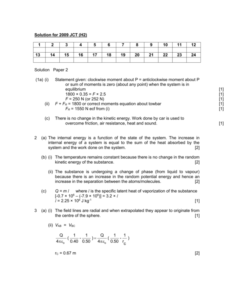
Solution for 2009 JCT (H2) 1 2 3 4 5 6 7 8 9 10 11 12 13 14 15 16 17 18 19 20 21 22 23 24 Solution Paper 2 (1a) (i) (ii) (c) 2 Statement given: clockwise moment about P = anticlockwise moment about P or sum of moments is zero (about any point) when the system is in equilibrium 1800 × 0.35 = F × 2.5 F = 250 N (or 252 N) F + FR = 1800 or correct moments equation about towbar FR = 1550 N ecf from (i) [1] [1] [1] [1] [1] There is no change in the kinetic energy. Work done by car is used to overcome friction, air resistance, heat and sound. [1] (a) The internal energy is a function of the state of the system. The increase in internal energy of a system is equal to the sum of the heat absorbed by the system and the work done on the system. [2] (b) (i) The temperature remains constant because there is no change in the random kinetic energy of the substance. [2] (ii) The substance is undergoing a change of phase (from liquid to vapour) because there is an increase in the random potential energy and hence an increase in the separation between the atoms/molecules. [2] (c) 3 Q=ml where l is the specific latent heat of vaporization of the substance [-0.7 × 10⁶ – (-7.9 × 10⁶)] = 3.2 × l l = 2.25 × 10⁶ J kg-1 [1] (a) (i) The field lines are radial and when extrapolated they appear to originate from the centre of the sphere. [1] (ii) VAB = VBC Q 1 1 Q 1 1 ( ) ( ) 4o 0.40 0.50 4o 0.50 r c rC = 0.67 m [2] (b) Horizontal component of v remains constant since no force acts in this direction. An electric force acts on the proton downward. So the vertical component of v increases uniformly downward with time. Hence the proton describes a parabolic path in the plane of the paper as shown. [4] path of proton E 4(a) px = 15.0 kg m s-1 px = mx vX 15.0 = mx (3.0) => mx = 5.0 kg (b) time t /s 0.25 0.30 0.35 0.40 momentum of trolley X, px / kg m s-1 15.0 10.0 5.8 5.0 (c) (d) (i) <ax> = 2.85 1.00 = -13.7 m s-2 0.250 0.385 Velocity of X, vx / m s-1 3.0 2.0 1.2 1.0 (ii) (e) sx = area under v-t graph = ½ (2.85 + 0.80) (0.40 - 0.25) = 0.27 m By conservation of momentum, px + pY = px’ + pY’ 15.0 + 2.0(1.5) = 5.0 + pY’ pY’ = 13 kg m s-1 to the right (f) min EPE = change in total KE of masses = ½ mx (vx’2 – vx2) + ½ mY (vY’2 – vY2) = ½ (5.0) (1.02 – 3.02) + ½ (2.0) [(13/2.0)2 – 1.52] = 20J Section C 1 (a) (b) Correct shape (concentric circles) with increasing separation [1] Direction correct [1] (i) Torque on coil due to magnetic force F d NBIL sin d 40 0.60 2.0 103 0.02 sin 90o 0.02 [1] [1] = 1.92 x 10⁻⁵ N m [1] (ii) By having the magnetic field always parallel to the plane of the coil, the torque on the coil would then be only dependent on the current in the coil. This ensures that the angle of deflection of the pointer would be proportional to current. [1] 1 (c) (i) After the magnet is released, it accelerates under gravity and its velocity increases. When the magnet approaches the coil, the magnetic flux linking the coil increases. According to Faraday’s law, an induced emf is produced which increases to a maximum when the N-pole of the magnet reaches the coil. By Lenz’s law, the direction of the induced emf opposes the increasing flux.[1] After the S-pole leaves the coil, the magnetic flux linking the coil reduces and the induced emf is greater in magnitude due to the higher speed of the magnet.[1] This emf is also in opposite direction compared to that for incoming magnet.[1] (ii) 1. As the magnet moves downwards, the induced emf produced would generate an induced current in the coil [1] which flows in such a way as to produce an induced Magnetic field which exerts an upward magnetic force on the magnet.[1] 2. Since an induced current is produced in the coil, electrical energy must be generated in the coil. [1]Loss in p.e. of magnet is converted to gain in k.e. of magnet plus electrical energy generated in coil. Hence, lesser amount of k.e. is gained by the magnet. So it is slower than before.[1] (iii) 1. e.m.f./V 2.50 1.25 0 -1.25 -2.50 0 t/ms 100 200 300 400 300 400 [1] for greater magnitude [1] for same time interval 2. e.m.f./V 2.50 1.25 0 -1.25 -2.50 0 t/ms 100 200 [1] for greater magnitude [1] for later time (d) (i) P IV P 4200 kW I 382 A V 11 kV [2] (ii) For transformer U, N s Vs 11 0.040 N p V p 275 [1] 2(a)(i) E hc 6.63 10 34 3.0 10 8 254 10 9 7.83 10 19 J 2(a)(ii) ET N ( )hf t t N P 210 12 10 6 t hf 7.83 10 19 3.22 1015 s 1 P 2(a)(iii) N' )e t 2.7 1013 1.6 10 19 I ( 4.32 10 6 A 2(b)(i) Stopping potential is the potential difference that must be applied between the cathode and the anode so that the most energetic photoelectron emitted just fails to reach the anode. [1] From eVs h 2(b)(ii) c If light of higher wavelength was used, the energy of the photons would decrease. Since the work function Ø is unchanged (same metal used), the kinetic energy of the emitted electrons would decrease. Hence the stopping potential would decrease. [3] I 2(b)(iii) 1. λ = 254 nm 2. λ > 254 nm V 0 (c) (i) (ii) [3] Since the energy levels are discrete (quantized), electron transitions between the levels involve absorption or emission of photons of discrete/specific wavelengths resulting in spectral lines. [2] 1. Energy of photon = hc = 6.63x10 -34 x 3.00 x 10 8 = 4.56 x10⁻¹⁹ J 9 436x10 = 2.85 eV Since E4 – E2 = 2.85 eV, the transition is from E4 to E2. 2. [3] The bombarding electron must have a minimum kinetic energy of 13.06 eV in order for the hydrogen atom to be excited from the ground state E1 to E4. Only then can a transition E4 to E2 take place. So the minimum value of V is 13.06 V. [2]

