tut10
advertisement
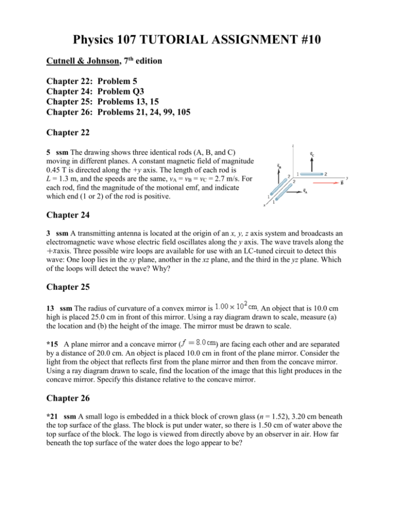
Physics 107 TUTORIAL ASSIGNMENT #10 Cutnell & Johnson, 7th edition Chapter 22: Chapter 24: Chapter 25: Chapter 26: Problem 5 Problem Q3 Problems 13, 15 Problems 21, 24, 99, 105 Chapter 22 5 ssm The drawing shows three identical rods (A, B, and C) moving in different planes. A constant magnetic field of magnitude 0.45 T is directed along the +y axis. The length of each rod is L = 1.3 m, and the speeds are the same, vA = vB = vC = 2.7 m/s. For each rod, find the magnitude of the motional emf, and indicate which end (1 or 2) of the rod is positive. Chapter 24 3 ssm A transmitting antenna is located at the origin of an x, y, z axis system and broadcasts an electromagnetic wave whose electric field oscillates along the y axis. The wave travels along the axis. Three possible wire loops are available for use with an LC-tuned circuit to detect this wave: One loop lies in the xy plane, another in the xz plane, and the third in the yz plane. Which of the loops will detect the wave? Why? Chapter 25 13 ssm The radius of curvature of a convex mirror is . An object that is 10.0 cm high is placed 25.0 cm in front of this mirror. Using a ray diagram drawn to scale, measure (a) the location and (b) the height of the image. The mirror must be drawn to scale. *15 A plane mirror and a concave mirror ( ) are facing each other and are separated by a distance of 20.0 cm. An object is placed 10.0 cm in front of the plane mirror. Consider the light from the object that reflects first from the plane mirror and then from the concave mirror. Using a ray diagram drawn to scale, find the location of the image that this light produces in the concave mirror. Specify this distance relative to the concave mirror. Chapter 26 *21 ssm A small logo is embedded in a thick block of crown glass (n = 1.52), 3.20 cm beneath the top surface of the glass. The block is put under water, so there is 1.50 cm of water above the top surface of the block. The logo is viewed from directly above by an observer in air. How far beneath the top surface of the water does the logo appear to be? 24 A point source of light is submerged 2.2 m below the surface of a lake and emits rays in all directions. On the surface of the lake, directly above the source, the area illuminated is a circle. What is the maximum radius that this circle could have? 99 ssm The drawing shows a crown glass slab with a rectangular cross section. As illustrated, a laser beam strikes the upper surface at an angle of 60.0°. After reflecting from the upper surface, the beam reflects from the side and bottom surfaces. (a) If the glass is surrounded by air, determine where part of the beam first exits the glass, at point A, B, or C. (b) Repeat part (a), assuming that the glass is surrounded by water. 105 ssm The drawing shows a coin resting on the bottom of a beaker filled with an unknown liquid. A ray of light from the coin travels to the surface of the liquid and is refracted as it enters into the air. A person sees the ray as it skims just above the surface of the liquid. How fast is the light traveling in the liquid? Solutions Chapter 22 5. SSM WWW REASONING AND SOLUTION For the three rods in the drawing, we have the following: Rod A: The motional emf is zero , because the velocity of the rod is parallel to the direction of the magnetic field, and the charges do not experience a magnetic force. Rod B: The motional emf is, according to Equation 22.1, = vBL (2.7 m/s)(0.45 T)(1.3 m) = 1.6 V The positive end of Rod B is end 2 . Rod C: The motional emf is zero , because the magnetic force F on each charge is directed perpendicular to the length of the rod. For the ends of the rod to become charged, the magnetic force must be directed parallel to the length of the rod. Chapter 24 Q3. SSM REASONING AND SOLUTION A transmitting antenna is located at the origin of an x, y, z axis system, and broadcasts an electromagnetic wave whose electric field oscillates along the y axis. The wave travels along the +x axis. Three possible loops can be used with an LC-tuned circuit to detect the wave: One loop lies in the xy plane, another in the xz plane, and the third in the yz plane. The loop that will detect the electromagnetic wave must be oriented so that the normal to the loop is parallel to the magnetic field. Then, as the wave passes by the loop, the changing magnetic field penetrates the loop and results in an induced emf and current, as predicted by Faraday's law. Since the electromagnetic wave travels along the +x direction, and the electric field oscillations of the electromagnetic wave are along the y axis, the magnetic field oscillations will be along the z axis. For optimum reception, therefore, the loop should lie in the xy plane so that the normal to the loop is in the z direction. Chapter 25 13. SSM REASONING AND SOLUTION The ray diagram is shown below. (Note: f –50.0 cm and do 25.0 cm ) Scale Reflected ray 10.0 cm Virtual Image Object 6.67 cm 10.0 cm 25.0 cm F 16.7 cm C a. The ray diagram indicates that the image is 16.7 cm behind the mirror . b. The ray diagram indicates that the image height is 6.67 cm . ______________________________________________________________________________ 15. REASONING AND SOLUTION A plane mirror faces a concave mirror ( f 8.0 cm ). The following is a ray diagram of an object placed 10.0 cm in front of the plane mirror. Incident ray Reflected ray Object Image from plane mirror F Scale: 5.0 cm Plane mirror Image from concave mirror Concave mirror The ray diagram shows the light that is first reflected from the plane mirror and then the concave mirror. The scale is shown in the figure. For the reflection from the plane mirror, as discussed in the text, the image is upright, the same size as the object, and is located as far behind the mirror as the object is in front of it. When the reflected ray reaches the concave mirror, the ray that is initially parallel to the principal axis passes through the focal point F after reflection from the concave mirror. The ray that passes directly through the focal point emerges parallel to the principal axis after reflection from the concave surface. The point of intersection of these two rays locates the position of the image. By inspection, we see that the image is located at 10.9 cm from the concave mirror. Chapter 26 21. SSM REASONING The drawing at the right shows the situation. As discussed in the text, when the observer is directly above, the apparent depth d of the object is related to the actual depth by Equation 26.3: n d d 2 n1 dw = 1.50 cm water (nw = 1.333 ) dg = 3.20 cm glass (ng = 1.52 ) logo In this case, we must apply Equation 26.3 twice; once for the rays in the glass, and once again for the rays in the water. SOLUTION We refer to the drawing for our notation and begin at the logo. To an observer in the water directly above the logo, the apparent depth of the logo is d g d g nw / ng . When viewed d w d w d g directly from above in air, the logo’s apparent depth is, nair / nw , where we have used the fact that when viewed from air, the logo’s actual depth appears to be d w d g . Substituting the expression for d g into the expression for d w , we obtain n d w (d w d g ) air n w nair d w nw n n w air d g n n g w nair d w nw n air d g n g 1.000 1.000 1.50 cm 3.20 cm 3.23 cm 1.333 1.52 24. REASONING AND SOLUTION Only the light which has an angle of incidence less than or equal c can escape. This light leaves the source in a cone whose apex angle is 2c. The radius of this cone at the surface of the water (n = 1.333, see Table 26.1) is R = d tan c. Now 1.000 c sin 1 48.6 1.333 So R = (2.2 m) tan 48.6° = 2.5 m 99. SSM REASONING AND SOLUTION a. Using Equation 26.4 and the refractive index for crown glass given in Table 26.1, we find that the critical angle for a crown glass-air interface is 1.00 41.0 1.523 c sin 1 The light will be totally reflected at point A since the incident angle of 60.0° is greater than c. The incident angle at point B, however, is 30.0° and smaller than c. Thus, the light will exit first at point B . b. The critical angle for a crown glass-water interface is 1.333 61.1 1.523 c sin 1 The incident angle at point A is less than this, so the light will first exit at point A . 105. SSM REASONING We will use the geometry of the situation to determine the angle of incidence. Once the angle of incidence is known, we can use Snell's law to find the index of refraction of the unknown liquid. The speed of light v in the liquid can then be determined. SOLUTION From the drawing in the text, we see that the angle of incidence at the liquidair interface is 5.00 cm 1 tan –1 39.8 6.00 cm The drawing also shows that the angle of refraction is 90.0°. Thus, according to Snell's law (Equation 26.2: n1 sin 1 n2 sin 2 ), the index of refraction of the unknown liquid is n1 n2 sin 2 (1.000) (sin 90.0) 1.56 sin1 sin 39.8 From Equation 26.1 ( n c / v ), we find that the speed of light in the unknown liquid is c 3.00 10 8 m/s v 1.92 10 8 m/s n1 1.56
