Congestion Problem
advertisement
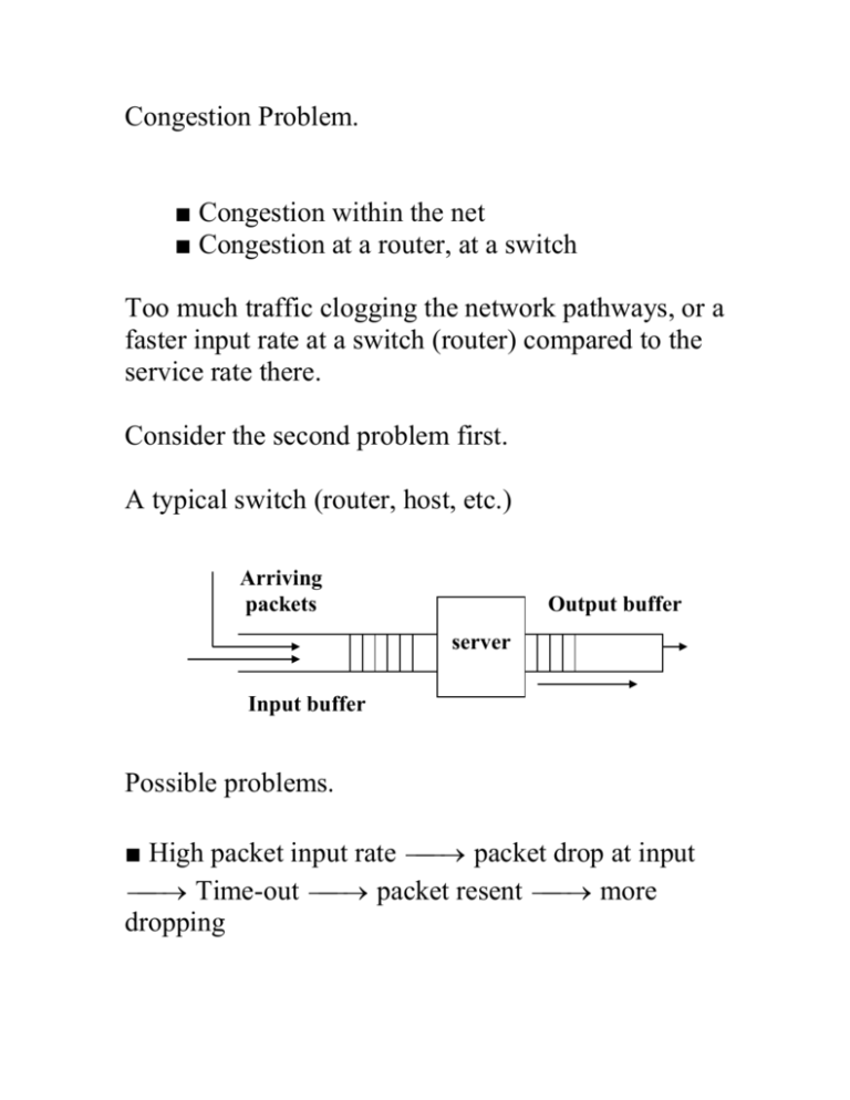
Congestion Problem. ■ Congestion within the net ■ Congestion at a router, at a switch Too much traffic clogging the network pathways, or a faster input rate at a switch (router) compared to the service rate there. Consider the second problem first. A typical switch (router, host, etc.) Arriving packets Output buffer server Input buffer Possible problems. ■ High packet input rate packet drop at input Time-out packet resent more dropping ■ Assume more input buffer. More input buffer more packets in buffer packets take more time to appear at front of the queue Time-out at the sender more packets re-sent ■ slow server packets take more time to appear at the front of queue Time-out at the sender more packets re-sent ■ Not enough output buffer packets are dropped at output buffer before being sent out Time-out at the sender more packets resent In general, congestion occurs when existing resources cannot cope with the traffic load (takes more time to move traffic) Packets delivered Pre-cong Congestion Packets injected Congestion control issue. Two types of solutions: Open loop control / Closed Loop Control. Open Loop approach: ■ Emphasis is on Congestion prevention and avoidance. ■ Design the system so well that congestion doesn’t take place. There’d be no midstream correction once the system is commissioned. ■ Tools for Open-loop design: ● when to accept new traffic? ● when to discard packets and which ones? ● how frequently routing tables should be sent? And, to whom? Closed Loop approach: Negative Feedback Loop Cong ? SYSTEM action Minimize congestion ■ Monitor the system to detect when and where congestion occurs. How many monitors and where? Stand-alone? Or, A cooperative set of monitors? How often should they communicate with each other? monitor ■ Pass the information to places where action can be taken. (If congestion is already set in how could info be sent to the appropriate router/host?) ■ Tweak system parameters to control the system correctly. Problem: Congestion is a global problem; system correction and tweaking are local effort. To detect congestion: Monitor ● percentage of packet drops at a buffer ● the average queue length or buffer occupancy ● The level of retransmissions due to packet time-out ● The average packet delay in a given domain ● The variance of packet delay To inform the offending station/router that something is amiss: ● Detecting router send a packet to the sender router to throttle its output traffic. Can such a packet be delivered when congestion is acute? ● Alternatively, consider a packet like this Source addres s Dest. addres s Control field Congestion bit Pay load Typical Packet A router discovering congestion inserts a bit 1 In the congestion bit field of a packet to warn its neighbors. ● Or, send probes to neighbors periodically. From the probe results recreate traffic profile. If congestion is detected, bypass that area for immediate traffic. In general, to handle congestion in a region: ● Either, find additional resources for the region (like more lines, more bandwidth, more buffer, ..) ● Or, discourage the nodes responsible for congestion to send new packets, terminate some sessions, some specific traffics … Congestion problem has to be attended at all levels of protocol layers for open-loop system design. In particular: At Data-link layer, attend to: ● Retransmission policy: How fast should sender time-out and retransmit its frame? If too fast, if “Go back to n” policy used, it’d put more load in the system. ● Out-of-order caching policy: ● Acknowledgement policy: How about piggybacking on reverse traffic to send ACKs? ● Flow Control policy: How about allowing at most m frames to remain unacknowledged before next frame is delivered? At Network layer, attend to ● Virtual circuits vs datagrams inside the net: (Many congestion avoidance algorithms work only with virtual circuits) ● Packet queuing and service policy: How many queues for input traffic, how many queues for outgoing traffic? How are the packets served? FIFO? Priority based? ● Packet discard policy: Which packets need to be dropped when buffer is full? The newer packets? The older packets? ● Packet lifetime management: Large TTL value for a packet allows it a longer time before it dies. This prevents packets from being destroyed before it reaches its destination. However, if it is too long, packets will clog up the network. At Transportation layer level, attend to ● Retransmission policy: Here, it is end-to-end retransmission policy. Time-out period is difficult to estimate as it would have a higher variance. ● Out-of-order caching policy ● Acknowledgement policy ● Flow control policy ● Time-out determination: Same for every flow? Differential specification? Congestion control is concerned with running a network efficiently at a high load. Several techniques are available to accomplish this (we already discussed some of them) ● Warning bit ● Choke packets ● Load shedding ● Random early discard ● Traffic shaping First three approaches the problem essentially as congestion detection and recovery. The last two deals with congestion avoidance. Traffic shaping Normal traffic from a source is bursty. And this creates a problem. Bytes transmitted Average Time Bursty traffic contributes to a high variance. Ideally, one should have a more predictable packet transmission over a period. To do this, we need a Traffic shaper. ATM networks use this scheme. A Traffic shaper more uniform traffic. Analogy. Leaky bucket. Bursty Water flow Leaky bucket Water drips at a Constant rate We could do same with bursty packet flows. Unregulated flow Traffic Shaper Regulated Flow Leaky bucket algorithm. ■ Each host has a finite buffer at its interface to the network. ■ A new packet entering the interface is discarded if the buffer is full. ■ Otherwise, it gets into the buffer. The buffer injects some n bytes of payload per unit clock-time. Therefore, if n is 1024 bytes, injection rate at the interface is: packet size 1024 512 256 number of packets 1 2 4 Token bucket algorithm Similar to Leaky bucket algorithm. Tokens arrive into a bucket. Host can transmit its packet if and only if it has a token captured. host host Packets from host Tokens in the bucket Network interface Assume packets are injected into the system in bursts and burst-length is S sec. S Packet bursts time Assume also tokens arrive at the bucket at a rate of token per sec. Assume C = bucket capacity in bytes M = Maximum injection rate (output rate) in bytes/sec. Then, C S MS or S C M To get a smoother traffic, one can insert a leaky bucket after a token bucket host Packets from host Tokens in the bucket Leaky bucket Network interface Ultimately, routers have to do a lot to overcome potential congestion problems. Traffic shaping is done at the host level. Routers need to do ● congestion signaling ● packet drops ● buffer management ● marking packets We did cover all these. Additionally, we could do some more. ● RED: Random Early Detection. drop nothing drop some with p drop all maximum probability Average queue length RED is an active queue management scheme. Try to keep it small so that average queuing time within the queue is small but large enough to service many different flows. For instance, in an M / M / 1 queue: Assume, router Router queue ● average packet arrival rate = pkts/sec ● average packet size = 1 bits ● channel capacity (max number of bits it can transmit, C bits/sec then queue parameters are: ● average service time = 1 sec C ● server utilization (traffic density) is C ● average number of packets in the system L 1 pkts ● average residence time (total time) in the system per pkt T 1 1 C C( 1 ) ● average queuing time per pkt Tq T 1 C C( 1 ) ● average number of pkts in the queue only 2 Lq 1 Note that if Lq is high, it means 1. With that , the average queuing time Tq becomes very large compelling some hosts to time-out and retransmit. RED drops out packets earlier than when the queue is full. Also, RED randomizes the packets to be dropped so that synchronizations and biases are avoided. RED rule: ● set up Lmax and Lmin ● qa = average queue size ● if qa Lmin , admit incoming packet in the buffer if qa Lmax , drop the incoming packet else drop the packet with a probability pa For packets encountering qa Lmin , we consider them unmarked. Otherwise, it would be marked. We compute qa as follows: qanow ( 1 wq )qalast wq q where q = transient queue as actually seen wq = a constant between 0.0 and 1.0 If wq is closer to 1.0, we’d be making decision based on transient queue value q . If wq 0.0, we would smooth out transients and make decisions sluggishly. To compute pa , qa Lmin , where b is a constant Lmax Lmin ● having pb , we compute pa in the following way: ● compute pb b ■ Method 1: pa pb . ■ Method 2: pa pb where count is 1 count pb the count of number of unmarked packets since the last marked packet. How do we choose Lmax ? This should not be too large, since after qa Lmax the packets will be dropped anyway. However, a small Lmax may make the behavior of pb rather abrupt and discontinuous at qa Lmax . For more info: http://www.cs.ucsb.edu/~almeroth/classes/S00.276/p apers/red.pdf Several variations of RED have emerged lately. ■ Gentle RED (where transition from probabilistic to always drop is not so sudden) ■ ARED (Adaptive Random Early Detection) (Read: A study of Active Queue Management for Congestion Control by Victor Firoiu and Marty Borden) http://citeseer.ist.psu.edu/cache/papers/cs/12977/http: zSzzSzwww.ieeeinfocom.orgzSz2000zSzpaperszSz405.pdf/firoiu00st udy.pdf
