G4MICE Features
advertisement
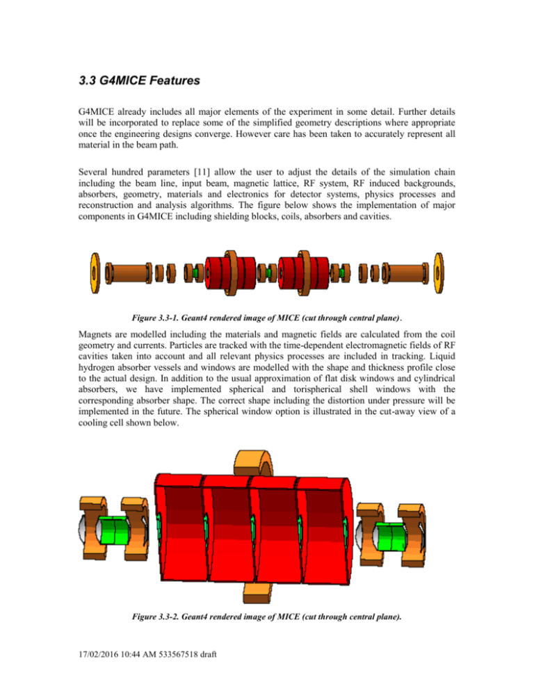
3.3 G4MICE Features G4MICE already includes all major elements of the experiment in some detail. Further details will be incorporated to replace some of the simplified geometry descriptions where appropriate once the engineering designs converge. However care has been taken to accurately represent all material in the beam path. Several hundred parameters [11] allow the user to adjust the details of the simulation chain including the beam line, input beam, magnetic lattice, RF system, RF induced backgrounds, absorbers, geometry, materials and electronics for detector systems, physics processes and reconstruction and analysis algorithms. The figure below shows the implementation of major components in G4MICE including shielding blocks, coils, absorbers and cavities. Figure 3.3-1. Geant4 rendered image of MICE (cut through central plane) . Magnets are modelled including the materials and magnetic fields are calculated from the coil geometry and currents. Particles are tracked with the time-dependent electromagnetic fields of RF cavities taken into account and all relevant physics processes are included in tracking. Liquid hydrogen absorber vessels and windows are modelled with the shape and thickness profile close to the actual design. In addition to the usual approximation of flat disk windows and cylindrical absorbers, we have implemented spherical and torispherical shell windows with the corresponding absorber shape. The correct shape including the distortion under pressure will be implemented in the future. The spherical window option is illustrated in the cut-away view of a cooling cell shown below. Figure 3.3-2. Geant4 rendered image of MICE (cut through central plane). 17/02/2016 10:44 AM 533567518 draft Geometry and materials are implemented in detail for all the detectors. A cross section of the layout is shown below with scintillating fibre tracker planes and downstream particle ID detectors. Figure 3 3-3. Geant4 rendered image of MICE (cut through central plane). The simulation chain includes inefficiencies and noise in the signal paths when digitizing hits to form the raw output data and parameter values obtained from prototype tests are being fed back into the model to improve realism. The full chain including reconstruction of tracks has been implemented for the baseline scintillating fibre tracker. Detailed geometry and readout electronics for the TPG option is also included in G4MICE. In addition to its internal beam generator that allows the user to specify the beam kinematics, time structure and purity, G4MICE accepts the output of several other programs as its input beam including ICOOL, G4Beamline and TURTLE. This allows the beam line transport calculation to be done externally by other programs that are better suited for that purpose and inclusion of the results directly in the simulation. The output format is currently in simple ASCII form. When a detailed design of the data acquisition system including a trigger definition and output format are available, an appropriate interface will be defined. The intent is for the G4MICE digitization output to look exactly like raw data from the DAQ system. A fairly detailed and flexible RF background model has been implemented to investigate the effect of backgrounds from field emission electrons originating in RF cavities and will be using parameters measured from the commissioning of prototype cavities. The model supports an arbitrary number of planes that are specified by the user in an input file. The position and radius of each of these background planes can be set separately. On each background plane, one can specify the particle type (electron, photon or both), mean number of particles per RF pulse, direction of particle emission (left, right or both), and a histogram of particle energies, relative phases and weights. Both discrete and continuous energy spectra are supported. The transverse position of the emitted particles is uniformly distributed over the background plane. This model captures the essential features of field emission from the pillbox shaped RF cavities with large flat surfaces in the MICE cooling channel. The emission from these background planes is superimposed with the beam muon in each event to accurately model the effect on detector occupancies and tracking performance. The projected rates in MICE require generation of over 2000 background electrons per beam muon in simulation. Tracking so many particles in each simulated event is very inefficient since very few of them reach the detectors and deposit energy. Currently, a three-step approach is used for modelling a realistic rate in the simulation. First, an external calculation is used to follow electrons from individual internal cavity window surfaces to the outer boundary of each 4-cavity accelerating section. Electrons are generated at each surface when the electric field is at its peak during the RF half cycle when it's pointing toward that surface. The cavity fields are phased for acceleration of 200 MeV/c muons and the electrons are tracked through the cavities with the proper relative cavity phases and energy loss in the Be cavity windows taken into account. After all the possible combinations are exhausted (emission from all the internal surfaces repeated over many RF cycles), a list of electron energies and arrival times are saved at each end of the accelerating sections. This set has realistic energy 17/02/2016 10:44 AM 533567518 draft spectrum and phase information and is appropriate for use as input background planes to the Geant4 simulation. These background particles are tracked all the way through the channel. All the particles that exit the cooling section toward the detectors are saved at reference planes before each tracker during production runs with large statistics. A large set of such particles saved at the reference planes are then added as background to runs with a muon beam. The internal tracking of field emission electrons from cavity surfaces will be incorporated into the Geant4 simulation in the future without need for an external calculation. This will allow a more accurate simulation of electron transport including the shape of the cavity interior as well as electric and magnetic field maps. 17/02/2016 10:44 AM 533567518 draft


