Chapter 3 - North Logan City
advertisement
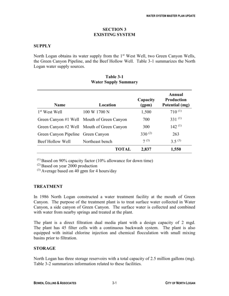
WATER SYSTEM MASTER PLAN UPDATE SECTION 3 EXISTING SYSTEM SUPPLY North Logan obtains its water supply from the 1st West Well, two Green Canyon Wells, the Green Canyon Pipeline, and the Beef Hollow Well. Table 3-1 summarizes the North Logan water supply sources. Table 3-1 Water Supply Summary Capacity (gpm) Annual Production Potential (mg) 1,500 710 (1) Green Canyon #1 Well Mouth of Green Canyon 700 331 (1) Green Canyon #2 Well Mouth of Green Canyon 300 142 (1) 330 (2) 263 7 (3) 3.5 (3) 2,837 1,550 Name st 1 West Well Location 100 W 1700 N Green Canyon Pipeline Green Canyon Beef Hollow Well Northeast bench TOTAL (1) Based on 90% capacity factor (10% allowance for down time) Based on year 2000 production (3) Average based on 40 gpm for 4 hours/day (2) TREATMENT In 1986 North Logan constructed a water treatment facility at the mouth of Green Canyon. The purpose of the treatment plant is to treat surface water collected in Water Canyon, a side canyon of Green Canyon. The surface water is collected and combined with water from nearby springs and treated at the plant. The plant is a direct filtration dual media plant with a design capacity of 2 mgd. The plant has 45 filter cells with a continuous backwash system. The plant is also equipped with initial chlorine injection and chemical flocculation with small mixing basins prior to filtration. STORAGE North Logan has three storage reservoirs with a total capacity of 2.5 million gallons (mg). Table 3-2 summarizes information related to these facilities. BOWEN, COLLINS & ASSOCIATES 3-1 CITY OF NORTH LOGAN WATER SYSTEM MASTER PLAN UPDATE Table 3-2 Storage Facilities Name Location Capacity (mg) Year Built Reservoir #1 Mouth of Green Canyon 0.5 1971 Reservoir #2 Mouth of Green Canyon 1.0 1995 Beef Hollow Reservoir Northeast bench 1.0 1995 TOTAL 2.5 DISTRIBUTION The North Logan water distribution system includes pipelines from 4 inches to 12 inches in diameter, totaling approximately 69,000 linear feet of pipe. The system is divided into six pressure zones. Flow from the higher zones to the lower zones is controlled by pressure reducing valves. The system includes three booster pumps as summarized in Table 3-3. The Beef Hollow Booster station pumps from Reservoir #2 to the upper northeast bench, filling the Beef Hollow Reservoir. Boosters # 1 and 2 are used in conjunction with the 1st West Well to pump water from the lower pressure zones to the upper pressure zones. Table 3-3 Booster Pumps Name Location Beef Hollow Booster Mouth of Green Canyon Booster #1 800 East 1800 North Booster #2 1700 East 1900 North SYSTEM MAP A map of the North Logan water system showing wells, storage reservoirs, distribution pipelines, booster pumps, and PRVs is presented in Figure 3-1. BOWEN, COLLINS & ASSOCIATES 3-2 CITY OF NORTH LOGAN
