80M Vertical Antenna with Capacitance Hat
advertisement
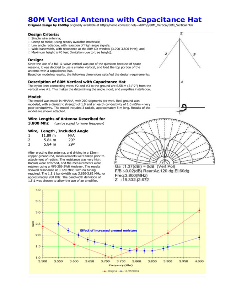
80M Vertical Antenna with Capacitance Hat Original design by kb0fhp originally available at http://home.comcast.net/~kb0fhp/80M_Vertical/80M_Vertical.htm Design Criteria: � � � � � Simple wire antenna; Cheap to make, using readily available materials; Low angle radiation, with rejection of high angle signals; Wide bandwidth, with resonance at the 80M DX window (3.790-3.800 MHz); and Maximum height is 40 feet (limitation due to tree height). Design: Since the use of a full ¼-wave vertical was out of the question because of space reasons, it was decided to use a smaller vertical, and load the top portion of the antenna with a capacitance hat. Based on modeling results, the following dimensions satisfied the design requirements: Description of 80M Vertical with Capacitance Hat The nylon lines connecting wires #2 and #3 to the ground are 6.58 m (21’-7”) from the vertical wire #1. This makes the determining the angle moot, and simplifies installation. Model: The model was made in MMANA, with 200 segments per wire. Real ground was modeled, with a dielectric strength of 1.0 and an earth conductivity of 1.0 mS/m – very poor conductivity. The model included 3 radials, approximately 5 m long. Results of the model are shown attached. Wire Lengths of Antenna Described for 3.800 Mhz (can be scaled for lower frequency) Wire, Length , Included Angle 1 11.89 m N/A 2 5.84 m 29º 3 5.84 m 29º After erecting the antenna, and driving in a 12mm copper ground rod, measurements were taken prior to attachment of radials. The resistance was very high. Radials were attached, and the measurements were retaken using a MFJ-259 SWR Analyzer. The results showed resonance at 3.720 MHz, with no tuning required. The 1.5:1 bandwidth was 3.620-3.82 MHz, or approximately 200 KHz. The bandwidth definition of 1.5:1 was chosen to allow the use of an amplifier. Effect of increased ground moisture

