F-R/2-07 típusú csőbiztosítás ( deflagrációzár )
advertisement
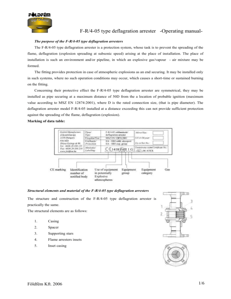
F-R/4-05 type deflagration arrester -Operating manualThe purpose of the F-R/4-05 type deflagration arresters The F-R/4-05 type deflagration arrester is a protection system, whose task is to prevent the spreading of the flame, deflagration (explosion spreading at subsonic speed) arising at the place of installation. The place of installation is such an environment and/or pipeline, in which an explosive gas/vapour - air mixture may be formed. The fitting provides protection in case of atmospheric explosions as an end securing. It may be installed only in such systems, where no such operation conditions may occur, which causes a short-time or sustained burning on the fitting. Concerning their protective effect the F-R/4-05 type deflagration arrester are symmetrical, they may be installed as pipe securing at a maximum distance of 50D from the a location of probable ignition (maximum value according to MSZ EN 12874:2001), where D is the rated connection size, (that is pipe diameter). The deflagration arrester model F-R/4-05 installed at a distance exceeding this can not provide sufficient protection against the spreading of the flame, deflagration (explosion). Marking of data table: Structural elements and material of the F-R/4-05 type deflagration arresters The structure and construction of the F-R/4-05 type deflagration arrester is practically the same. The structural elements are as follows: 1. Casing 2. Spacer 3. Supporting stars 4. Flame arresters insets 5. Inset casing Földfém Kft. 2006 1/6 F-R/4-05 type deflagration arrester -Operating manualConditions of the safe use of the F-R/4-05 type deflagration arresters - When installing the F-R/4-05 type deflagration arrester to the place of installation the location and tools of installation should be chosen with great care. - The deflagration arrester should be installed only in such a system, in which the formation of explosive gas/vapour - air mixture may be caused by a material belonging to the application category IIA, IIB1, IIB2, IIB3. - The deflagration arrester are symmetrical, they may be installed as pipe securing at a maximum distance of 50D from the a location of probable ignition (maximum value according to MSZ EN 12874:2001), where D is the rated connection size, (that is pipe diameter). The system before the fitting should preferably be of „turbulence free” design (omission of reducing pipes, branch pipes, etc.). - Concerning their protective effect the F-R/4-05 type deflagration arrester are symmetrical, so their installation is non-directed. - The fitting is may be installed only in a pipeline of dimension corresponding to the rated connection diameter (application of pipe reducer and/or inverted reducer is not allowed!). - When installed into the system no leakage is allowed along the joining flanges at an absolute pressure of 1.1 times absolute working pressure, but minimum 150 kPa. - The working pressure at the place of installation should not exceed the absolute pressure of 130 kPa=1,3 bar, when an inflammable gas/vapour – air concentration is present in the system! The allowable surface temperature of the deflagration arresters is min.: -20oC and max.: +60oC. - The pipeline in which the deflagration arrester is installed should not contain any solid matter of diameter exceeding 0.5 mm, because in case of deflagration it may seriously damage the protective elements of the fitting, which thus may lose their protective effect! - The fitting should be protected from „non-liquid” contaminations. Grains of diameter greater than 0.5 mm may cause clogging and/or pressure increase! When designing the location of installation a special emphasis should be laid on it. If necessary, the pressure drop should be measured on the fitting and/or filtering installation (e.g. pipe filter or filter bowl) should be applied. - In case of the failure of the deflagration arresters, its contamination, which cannot be eliminated by blowing out or flushing out with proper liquid stream, the dismantling, checking, reassembling and installation of the deflagration arresters may only be done by a person properly trained for this task. In case the operator has no such person, then a new deflagration arresters should be installed and the dismantled fitting should be returned to the manufacturer's site for being repaired. - If the installed deflagration arrester undergoes a deflagration burn, the entire fitting should be returned to the manufacturer for supervision. Földfém Kft. 2006 2/6 F-R/4-05 type deflagration arrester -Operating manual- If the deflagration arrester shows outward signs of damage, or deformations, it should immediately be returned to the manufacturer for supervision! - In case of assemblage for checking and cleaning purpose and removal of the deflagration arresters only such tools may be used, which correspond to the zone category, and not generating spark. Materials (e.g. wiping cloth) causing electrostatic charging should be avoided. - If the system having the deflagration arresters built in distributes a harmful material, then in case of opening the system due to removal, checking or cleaning purpose the health regulations (e.g. use of respiratory apparatus) should strictly be observed. Material quality: Housing : Flame protection unit: Seal: stainless-steel, carbon-steel stainless-steel, Hastelloy Teflon Other technical parameters: „Airspace” of flame protection unit:0,5 mm Number of flame protection unit: 4 Protection: IIA, IIB1, IIB2 and IIB3 gas group Distance from the a location of probable ignition: 50 x D (where D is the rated connection size) Labelling: MBF-TMB Műszaki Biztonsági Felügyelőség Certificate No.: to proceed BKI EX VÁ Robbanásbiztos Berendezéseket Vizsgáló Állomása Kft. Certificate No.: BKI 06 ATEX 047X Földfém Kft. 2006 3/6 F-R/4-05 type deflagration arrester -Operating manualDN15-DN32 Dimension table for DIN2633 flange connection Connection size Diameter of fleme filter „A” „B” „C” DN 15 65 mm 290 mm DN 20 65 mm 290 mm DN 25 65 mm 290 mm DN 32 65 mm 290 mm Dimension table for screw connection Connection size „A” Flow-technique measurings (DN15-DN32): Diameter of fleme filter „B” „C” „D” 1/2” 65 mm 146 mm 129 mm 3/4” 65 mm 146 mm 129 mm 1” 65 mm 146 mm 129 mm 5/4” 65 mm 146 mm 129 mm 10 q[m3/min] 1 DN32 0,1 1 10 100 p [mbar] 1000 This volume flow/pressure drop diagram has been measured on MSZ ISO 5167-1. The volume flow q in Nm3/min refers to air with density ρair=1,29 kg/m3 at a temperature T0=273 K and pressure p0=1000 mbar. Conversion factor method on different density media: Földfém Kft. 2006 Δp xy = (ρ xy / ρair) * Δpair 4/6 F-R/4-05 type deflagration arrester -Operating manualDN40-DN80 Dimension table for DIN2633 flange connection Connection size „A” Diameter of fleme filter „B” „C” „D” DN 40 104mm 320mm 138mm DN 50 104mm 320mm 138mm DN 65 152mm 366mm 182mm DN 80 152mm 366mm 182mm Dimension table for screw connection Connection size „A” Diameter of fleme filter „B” „C” „D” 6/4” 104mm 174mm 138mm 2” 104mm 174mm 138mm 2 1/2” 152mm 222mm 182mm 3” 152mm 222mm 182mm Flow-technique measurings (DN40-DN80): 100 3 q[m /min] 10 1 DN80 0,1 1 10 100 1000 p [mbar] This volume flow/pressure drop diagram has been measured on MSZ ISO 5167-1. The volume flow q in Nm3/min refers to air with density ρair=1,29 kg/m3 at a temperature T0=273 K and pressure p0=1000 mbar. Conversion factor method on different density media: Földfém Kft. 2006 Δp xy = (ρ xy / ρair) * Δpair 5/6 F-R/4-05 type deflagration arrester -Operating manualDN80-DN150 (welded construction) Dimension table for DIN2633 flange connection Connection size „A” Diameter of fleme filter „B” „C” „D” DN 80 152mm 226mm 200mm DN 100 200mm 238mm 220mm DN 125 240mm 275mm 250mm DN 150 285mm 295mm 285mm Flow-technique measurings (DN80-DN150): 1000 3 q[m /min] 100 10 DN150 1 0,1 1 10 100 p [mbar] 1000 This volume flow/pressure drop diagram has been measured on MSZ ISO 5167-1. The volume flow q in Nm3/min refers to air with density ρair=1,29 kg/m3 at a temperature T0=273 K and pressure p0=1000 mbar. Conversion factor method on different density media: Földfém Kft. 2006 Δp xy = (ρ xy / ρair) * Δpair 6/6
