Chapter 11 Solutions
advertisement

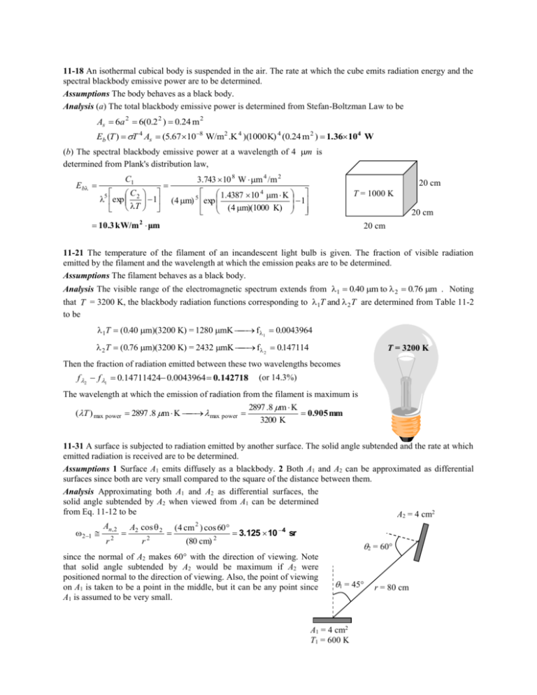
11-18 An isothermal cubical body is suspended in the air. The rate at which the cube emits radiation energy and the spectral blackbody emissive power are to be determined. Assumptions The body behaves as a black body. Analysis (a) The total blackbody emissive power is determined from Stefan-Boltzman Law to be As 6a 2 6(0.2 2 ) 0.24 m 2 Eb (T ) T 4 As (5.67 10 8 W/m2 .K 4 )(1000 K) 4 (0.24 m 2 ) 1.36 104 W (b) The spectral blackbody emissive power at a wavelength of 4 m is determined from Plank's distribution law, E b C1 C 5 exp 2 T 1 3.743 10 8 W m 4 /m 2 20 cm 1.4387 10 4 m K 1 (4 m) 5 exp (4 m)(1000 K) T = 1000 K 20 cm 10.3 kW/m μm 2 20 cm 11-21 The temperature of the filament of an incandescent light bulb is given. The fraction of visible radiation emitted by the filament and the wavelength at which the emission peaks are to be determined. Assumptions The filament behaves as a black body. Analysis The visible range of the electromagnetic spectrum extends from 1 0.40 m to 2 0.76 m . Noting that T = 3200 K, the blackbody radiation functions corresponding to 1T and 2 T are determined from Table 11-2 to be 1T (0.40 m)(3200 K) = 1280 mK f 1 0.0043964 2 T (0.76 m)(3200 K) = 2432 mK f 2 0147114 . T = 3200 K Then the fraction of radiation emitted between these two wavelengths becomes f 2 f 1 0.14711424 0.0043964 0.142718 (or 14.3%) The wavelength at which the emission of radiation from the filament is maximum is (T ) max power 2897 .8 m K max power 2897 .8 m K 0.905 mm 3200 K 11-31 A surface is subjected to radiation emitted by another surface. The solid angle subtended and the rate at which emitted radiation is received are to be determined. Assumptions 1 Surface A1 emits diffusely as a blackbody. 2 Both A1 and A2 can be approximated as differential surfaces since both are very small compared to the square of the distance between them. Analysis Approximating both A1 and A2 as differential surfaces, the solid angle subtended by A2 when viewed from A1 can be determined from Eq. 11-12 to be A2 = 4 cm2 An, 2 A cos (4 cm 2 ) cos 60 21 2 2 2 2 3.125 10 4 sr 2 r r (80 cm) 2 = 60 since the normal of A2 makes 60 with the direction of viewing. Note that solid angle subtended by A2 would be maximum if A2 were positioned normal to the direction of viewing. Also, the point of viewing 1 = 45 r = 80 cm on A1 is taken to be a point in the middle, but it can be any point since A1 is assumed to be very small. A1 = 4 cm2 T1 = 600 K The radiation emitted by A1 that strikes A2 is equivalent to the radiation emitted by A1 through the solid angle 2-1. The intensity of the radiation emitted by A1 is I1 E b (T1 ) T14 (5.67 10 8 W/m 2 K 4 )(800 K) 4 7393 W/m 2 sr This value of intensity is the same in all directions since a blackbody is a diffuse emitter. Intensity represents the rate of radiation emission per unit area normal to the direction of emission per unit solid angle. Therefore, the rate of radiation energy emitted by A1 in the direction of 1 through the solid angle 2-1 is determined by multiplying I1 by the area of A1 normal to 1 and the solid angle 2-1. That is, Q I ( A cos ) 1 2 1 1 1 2 2 1 (7393 W/m sr)( 4 10 4 cos 45 m 2 )(3.125 10 4 sr) 6.534 10 4 W Therefore, the radiation emitted from surface A1 will strike surface A2 at a rate of 6.53410-4 W. If A2 were directly above A1 at a distance 80 cm, 1 = 0 and the rate of radiation energy emitted by A1 becomes zero. 11-41 The variation of emissivity of a surface at a specified temperature with wavelength is given. The average emissivity of the surface and its emissive power are to be determined. Analysis The average emissivity of the surface can be determined from 2 1 (T ) 0 2 E b (T )d 1 E b (T )d 1 T 4 T 4 1 f 0-1 + 2 f 1 -2 + 3 f 2 - 3 E b (T )d 2 T 4 1 f 1 + 2 ( f 2 f 1 ) + 3 (1 f 2 ) 0.7 0.4 0.3 where f 1 and f 2 are blackbody radiation functions corresponding to 1T and 2 T , determined from 2 1T (2 m)(1000 K) = 2000 mK f 1 0.066728 , m 6 2 T (6 m)(1000 K) = 6000 mK f 2 0.737818 f 01 f 1 f 0 f 1 since f 0 0 and f2 f f 2 since f 1. and, (0.4)0.066728 (0.7)(0.737818 0.066728 ) (0.3)(1 0.737818 ) 0.575 Then the emissive power of the surface becomes E T 4 0.575(5.67 10 8 W/m2 .K 4 )(1000 K) 4 32.6kW/m2 11-61 The absorber plate of a solar collector is exposed to solar and sky radiation. The net rate of solar energy absorbed by the absorber plate is to be determined. Properties The solar absorptivity and emissivity of the surface are given to s = 0.87 and = 0.09. 600 W/m2 Air T = 25C Tsky = 15C Absorber plate Ts = 70C s = 0.87 = 0.09 Insulation Analysis The net rate of solar energy delivered by the absorber plate to the water circulating behind it can be determined from an energy balance to be q net q gain q loss q net s Gsolar (Ts 4 Tsky 4 ) h(Ts Tair ) Then, q net 0.87 (600 W/m 2 ) 0.09 (5.67 10 8 W/m 2 .K 4 ) (70 273 K) 4 (15 273 K) 4 (10 W/m K)(70 C 25 C) 2 36.5 W/m2 Therefore, heat is gained by the plate and transferred to water at a rate of 36.5 W per m2 surface area.


