334.80 Ampacity (NM)
advertisement
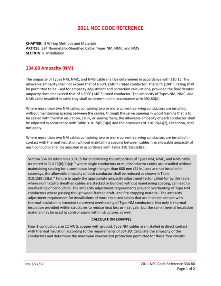
2011 NEC CODE REFERENCE CHAPTER: 3 Wiring Methods and Materials ARTICLE: 334 Nonmetallic-Sheathed Cable: Types NM, NMC, and NMS SECTION: II. Installation 334.80 Ampacity (NM) The ampacity of Types NM, NMC, and NMS cable shall be determined in accordance with 310.15. The allowable ampacity shall not exceed that of a 60°C (140°F) rated conductor. The 90°C (194°F) rating shall be permitted to be used for ampacity adjustment and correction calculations, provided the final derated ampacity does not exceed that of a 60°C (140°F) rated conductor. The ampacity of Types NM, NMC, and NMS cable installed in cable tray shall be determined in accordance with 392.80(A). Where more than two NM cables containing two or more current-carrying conductors are installed, without maintaining spacing between the cables, through the same opening in wood framing that is to be sealed with thermal insulation, caulk, or sealing foam, the allowable ampacity of each conductor shall be adjusted in accordance with Table 310.15(B)(3)(a) and the provisions of 310.15(A)(2), Exception, shall not apply. Where more than two NM cables containing two or more current-carrying conductors are installed in contact with thermal insulation without maintaining spacing between cables, the allowable ampacity of each conductor shall be adjusted in accordance with Table 310.15(B)(3)(a). Section 334.80 references 310.15 for determining the ampacities of Types NM, NMC, and NMS cable. As stated in 310.15(B)(3)(a): “ where single conductors or multiconductor cables are installed without maintaining spacing for a continuous length longer than 600 mm (24 in.) and are not installed in raceways, the allowable ampacity of each conductor shall be reduced as shown in Table 310.15(B)(3)(a).” Failure to apply the appropriate ampacity adjustment factor called for by this table, where nonmetallic-sheathed cables are stacked or bundled without maintaining spacing, can lead to overheating of conductors. The ampacity adjustment requirements prevent overheating of Type NM conductors where passing though wood-framed draft- and fire-stopping material. The ampacity adjustment requirement for installations of more than two cables that are in direct contact with thermal insulation is intended to prevent overheating of Type NM conductors. Not only is thermal insulation provided within structures to reduce heat loss or heat gain, but the same thermal insulation material may be used to control sound within structures as well. CALCULATION EXAMPLE Four 2-conductor, size 12 AWG, copper with ground, Type NM cables are installed in direct contact with thermal insulation according to the requirements of 334.80. Calculate the ampacity of the conductors and determine the maximum overcurrent protection permitted for these four circuits. Rev. 1/27/12 2011 NEC Code Reference 334.80 Page 1 of 2 SOLUTION Step 1. Determine the number of current-carrying conductors. According to 310.15(B)(3)(a), the number of current-carrying conductors is Step 2. Determine the initial ampacity of 12 AWG using 334.80 and Table 310.15(B)(16). Using the 90°C copper ampacity from Table 310.15(B)(16) for derating purposes, the ampacity (prior to derating) is 30 amperes. Step 3. Determine the adjusted ampacity of each NM cable due to direct contact with thermal insulation using Table 310.15(B)(3)(a), eight current-carrying conductors require an adjustment factor of 70 percent: Step 4. Determine the maximum permitted overcurrent device for each NM cable circuit in this example. Section 334.80 does not allow an ampacity greater than given in the 60°C column of Table 310.15(B)(16). And, according to the footnote of Table 310.15(B)(16), conductor sizes of 14 AWG through 10 AWG must also comply with 240.4(D). Section 240.4(D) limits a 12 AWG copper conductor to a maximum of 20 amperes. Therefore, the 21 amperes of adjusted ampacity must be further reduced or limited by being protected by an overcurrent device not to exceed 20 amperes. Thus, 20 amperes is the final ampacity for each current-carrying conductor of this problem, and the maximum overcurrent device permitted for each of the four circuits in NM cable is 20 amperes. Conclusion: This example points out that NM cable can be installed without spacing and placed within thermal insulation by not exceeding nine current-carrying conductors [70 percent adjustment factor of Table 310.15(B)(3)(a)]. By following similar installation practice as outlined in this example, this requirement will have little impact on most installations, whether installing groups of NM cable from panelboards or installing multiple NM cables down to ganged switches, as long as the quantity is limited to not more than nine current-carrying conductors. Rev. 1/27/12 2011 NEC Code Reference 334.80 Page 2 of 2

