THREADED FASTENERS AND POWER SCREWS
advertisement
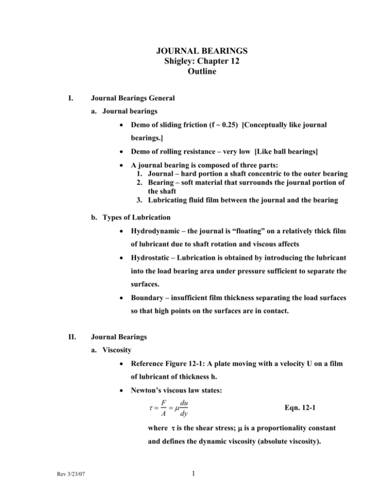
JOURNAL BEARINGS Shigley: Chapter 12 Outline I. Journal Bearings General a. Journal bearings Demo of sliding friction (f ~ 0.25) [Conceptually like journal bearings.] Demo of rolling resistance – very low [Like ball bearings] A journal bearing is composed of three parts: 1. Journal – hard portion a shaft concentric to the outer bearing 2. Bearing – soft material that surrounds the journal portion of the shaft 3. Lubricating fluid film between the journal and the bearing b. Types of Lubrication Hydrodynamic – the journal is “floating” on a relatively thick film of lubricant due to shaft rotation and viscous affects Hydrostatic – Lubrication is obtained by introducing the lubricant into the load bearing area under pressure sufficient to separate the surfaces. Boundary – insufficient film thickness separating the load surfaces so that high points on the surfaces are in contact. II. Journal Bearings a. Viscosity Reference Figure 12-1: A plate moving with a velocity U on a film of lubricant of thickness h. Newton’s viscous law states: F du A dy Eqn. 12-1 where is the shear stress; is a proportionality constant and defines the dynamic viscosity (absolute viscosity). Rev 3/23/07 1 du is the rate of change of velocity with distance above the dy stationary plate (y). Also, called the shear rate or velocity gradient. For most lubricants (Newtonian fluids) this equation can be written: F U A h Eqn. 12-2 where U is the upper plate velocity (max. velocity) and h is the distance between plates. Units of viscosity 1. reyn – ips system unit of viscosity (units: psi-sec) 2. The reyn is a very large unit of viscosity, so the micro reyn is often used. Specified as reyn or ' . 3. SI unit of dynamic viscosity is the Pascal –second: Pa-s. 4. Frequently viscosity is specified in centipoises, cp. Shigley uses Z as symbol for viscosity in cp. 5. Conversions: (Pa s) (10)3 Z (cp) (reyn) Z(cp) 6.89(10) 6 (mPa s) 6.89 ' ( reyn) [ ' is in micro reyn] Note: 1 cp = 1 mPa-s [a millipascal –second] 1. Saybolt Universal Viscosity (SUV) - a measure of kinematic viscosity. Kinematic viscosity is dynamic viscosity/density b. Petroff’s Equation Petroff’s equation is an approximate bearing equation for estimating bearing’s friction (or energy loss) f 2 ( 2 N r P )( ) c where f is the coefficient of friction Rev 3/23/07 2 N is the revolutions per second r is the journal radius (see fig. 12-3) c is the nominal clearance between journal and bearing P is the pressure generated by the weight or bearing load over the bearing projected area [2rl] where l is the length of the journal Although approximate, it contains two important dimensionless parameters relating to journal bearings: ( N r P )( ) . c These parameters are combined in a bearing characteristic number known as the Sommerfeld number, S: N r S( P 2 )( ) c Eqn. 12-7 Also, we can get the following equation: f r N r 2 2 2 ( )( ) = 2 2 S c P c Eqn. 12-8 Which relates Petroff’s coefficient of friction to the Sommerfeld No. c. Stable Lubrication There are three phases of film type lubrication (see handout) o Boundary – similar to sliding friction: high spots of rubbing surfaces are in contact; high friction similar to sliding friction demo in class. o Hydrodynamic - journal and bearing are separated by a “thick” film of lubricant. This film is relatively thick such that the journal “floats” on the liquid film and local asperities on the two surfaces do not touch (as they do in the boundary and mixed-film phases). o Mixed-Film – An intermediate condition between boundary and fully hydrodynamic lubrication. Rev 3/23/07 3 o The bearing coefficient of friction of these phases is a function of the non-dimensional number ( N P ) . Sample units for this number are: S I: - Pa-s ; N – 1/s ; P – Pa (N/m2 ) ips: - ryen (psi-s) ; N – 1/s ; P - psi A design constraint to keep thick film (or fully hydrodynamic) lubrication in a journal bearing is N P 6 1.7(10 ) d. Thick Film Lubrication Background At rest, the journal and bearing surfaces are in contact. This corresponds to the boundary lubrication condition As the journal starts to turn, it begins to drag lubricant under the journal. This is due to the viscous nature of the lubricant. As the journal rotates faster, it draws more lubricant under the journal and there is less and less contact between the two surfaces. This corresponds to the transition type lubrication With enough rotation speed, the journal draws sufficient fluid under it such that there is no contact between the two surfaces and the journal is “floating” on the liquid film. This corresponds to thick film or fully hydrodynamic lubrication. When operating in the hydrodynamic mode, the journal will not be centralized in the bearing so there is an eccentricity associated with hydrodynamic lubrication. (See figures: 12-5 and 12-6). The eccentricity ratio is defined as e where e is the distance between the center of the c journal and the center of the bearing. Rev 3/23/07 4 e. Hydrodynamic Theory Beauchamp Tower’s experiment – see figure 12-7. Early testing of journal bearing friction showed some surprising results. It became clear that the lubricant between the journal and bearing was under pressure. At sufficient rotational speed this pressure was enough to float the journal in the bearing. The pressure distribution was sufficient to support the journal (see figure 12-8). Reynolds one-dimensional flow equation Using the concept that the lubricant sticks to both the journal and bearing surfaces, Reynolds derives a one-dimensional flow equation. Reynolds made the following assumptions: Newtonian fluid, liquid inertia neglected, incompressible fluids, viscosity constant, and no pressure gradient along the axis. The derivation shown on pages 606 –609 gives: h 3 dp dh 6U x dx dx Eqn. 12-10 this equation assumes no lubricant leakage out of the bearing (no axial flow). This can be used for long bearings, but most modern bearings are not long so a more accurate analysis is needed. Extended Reynolds equation to case of side leakage gives h 3 dp h 3 dp h 6U x dx z dz x Eqn. 12-11 where z is the axial direction There is no general analytical solution to this equation. An approximate solution due to Sommerfeld can be expressed as r N r 2 f [( )( ) ] [ S ] c P c Eqn. 12-12 Where is a functional relationship. To solve equation 12-11 requires using non-dimensional groupings and charts: see charts 12-16,17,18,19,20,21,and 22. The abscissa in all these charts is the Sommerfeld number as in eqn. 12-12. Rev 3/23/07 5 f. Design Considerations Variable groupings Controllable variables o Viscosity, o Load per unit of projected bearing area, P o Speed, N o Bearing dimensions: r, c, , and l Indirectly controllable variables o Coefficient of friction, f o Temperature rise, T o Volume flow rate of oil, Q o Minimum film thickness, ho Minimum film thickness vs. journal bearing size ho 0.0002 + 0.00004d [units of inches] where d is the journal diameter (inches) and h is the minimum film thickness g. The variables relationship Viscosity vs. Temp. - See charts in figures: 12-12,12-13, 12-14 Viscosity very sensitive to temperature. Minimum film thickness variable vs. Sommerfeld – figure 12-16 Coefficient of Friction variable vs. Sommerfeld No. –Fig. 12-18 Flow Variable, ratio side to total flow, Film pressure ratio vs. Sommerfeld No. in figures: 12-19; 12-20; 12-21 See examples 12-1; 12-2; 12-3; and 12-4 h. Steady State Conditions Rev 3/23/07 See example 12-5 6 i. Clearance See figure 12-25 for variable relationship vs. radial clearance This figure shows the trade offs for good operation Preferred fits shown in tables 12-3 j. Pressure Fed Bearings Pressure fed bearings can be used to provide cooling With pressure fed bearings can’t use charts 12-19 and 12-20 See example 12-6 k. Loads and Materials Table 12-5 Range of loads in use for sleeve bearings Table 12-6 Alloys used in Bearings l. Bearing Types Sleeve bushings either solid or lined Two piece bushings: flanged or straight m. Thrust Bearings Pad type thrust bearings can have full hydrodynamic lubrication Normally journal bearings are radial only, but a flanged type bushing can have radial loads and thrust loads n. Boundary-Lubricated Bearings Boundary lubrication occurs whenever a journal bearing starts or stops. This is not a desirable condition as it is high friction and leads to wear. Some bearings are boundary lubricated (or dry) at all times. Examples: low speed bearings, oscillating journal, padded slides, light loads, and lifetime lubrication Rev 3/23/07 See example 12-7 7 For materials used in boundary or dry lubrication see table 12-7 Mixed-film lubrication is a condition between Boundary and fully hydrodynamic lubrication. It can be caused by limited lubricant or one of the following: 1. Low viscosity 2. Speed too low 3. Bearing is overloaded 4. Clearance is too tight 5. Poor alignment of journal and bearing Rev 3/23/07 8
