Cooling Tower Analysis
advertisement

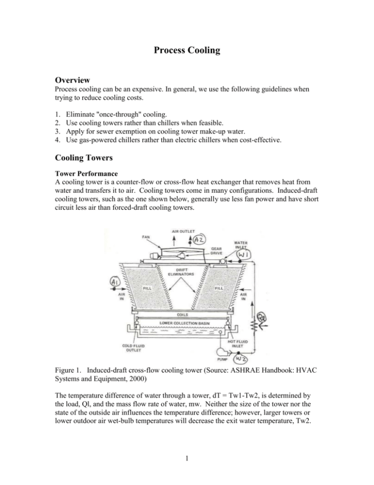
Process Cooling Overview Process cooling can be an expensive. In general, we use the following guidelines when trying to reduce cooling costs. 1. 2. 3. 4. Eliminate "once-through" cooling. Use cooling towers rather than chillers when feasible. Apply for sewer exemption on cooling tower make-up water. Use gas-powered chillers rather than electric chillers when cost-effective. Cooling Towers Tower Performance A cooling tower is a counter-flow or cross-flow heat exchanger that removes heat from water and transfers it to air. Cooling towers come in many configurations. Induced-draft cooling towers, such as the one shown below, generally use less fan power and have short circuit less air than forced-draft cooling towers. Figure 1. Induced-draft cross-flow cooling tower (Source: ASHRAE Handbook: HVAC Systems and Equipment, 2000) The temperature difference of water through a tower, dT = Tw1-Tw2, is determined by the load, Ql, and the mass flow rate of water, mw. Neither the size of the tower nor the state of the outside air influences the temperature difference; however, larger towers or lower outdoor air wet-bulb temperatures will decrease the exit water temperature, Tw2. 1 Typically, most towers are sized for a 10 F temperature difference and about 2.4 gpm/ton of cooling. Fan motor hp is about 0.1 hp/ton and air flow rates are about 2,000 cfm/hp. The temperature of water from a cooling tower, Tw2, can be calculated based on tower performance data such as that shown below, water flow rate, cooling load, and the ambient wet-bulb temperature. This process can be automated in software to predict cooling tower performance with varying ambient conditions. For example, CoolSim (Kissock, 1997) calculates exit water temperatures, and the fraction of time that a cooling tower can deliver water at a target temperature, based on entering water temperature, Tw1, and TMY2 weather data. This information is useful in determining how often a cooling tower can replace a chiller in cooling applications. Figure 2. Typical cooling tower performance curve (Source: ASHRAE Handbook: HVAC Systems and Equipment, 2000). Sensible and Latent Cooling Depending on the entering air and water temperatures, the water may be cooled by sensible and latent cooling of the air, or simply by latent cooling of the air. In either case, latent, i.e. evaporative, cooling is dominant. For example, consider the case in which the air enters at a lower temperature than the water (Figure 3a). The air will leave completely saturated and the cooling is part sensible and part latent. The sensible portion occurs as the air temperature increases by absorbing heat from the water. The latent portion occurs as some of the water evaporates, which draws energy out of the water. 2 If the air enters at the same wet bulb temperature as before, but at a higher dry-bulb temperature than the water, then the air will cool as it saturates (Figure 3b). Thus, the sensible cooling component is negative, and the all the cooling is due to evaporation. In general, cooling is dominated by latent cooling. Figure 3. Psychrometric process lines for air through a cooling tower, if the entering air temperature is a) less than the entering water temperature, and b) greater than the entering water temperature. The total cooling, ma (ha2 – ha1) is the same for both cases since enthalpy is a function of wet-bulb temperature alone. However, the dry-bulb temperature significantly influences the evaporation rate, mwe = ma (wa2-wa1). The rate of evaporation increases as the dry-bulb temperature increases for a given wet-bulb temperature. 3 Evaporation Rate As discussed in the previous section, cooling in cooling towers is dominated by evaporation. The evaporation rate can be calculated from the pyschrometric relations in the previous section, if the inlet and exit conditions of the air are known. For example, consider the case in which the cooling load, Ql, mass flow rate of air, ma, (which can be calculated based on the fan cfm and specific volume of the inlet air), and inlet conditions of air are known. The enthalpy of the exit air, ha2, can be calculated from an energy balance. Ql = ma (ha2 – ha1) ha2 = ha1+ Ql / ma The state of the exit air can be fixed by assuming that it is 100% saturated with an enthalpy ha2. The evaporation rate, mwe, can be determined by a water mass balance on the air. mwe = ma (wa2- wa1) The fraction of water evaporated is: mwe / mw Using this method for entering air temperatures from 50 F to 90 F, we determined that the fraction of water evaporated typically ranges from about 0.5% to 1%, with an average value of about 0.75%. Another way to estimate the fraction of water evaporated is to assume that all cooling, Ql, is from evaporation, Qevap. The cooling load Ql, is the product of the water flow rate, mw, specific heat, cp, and temperature difference, dT. The evaporative cooling rate is the product of the water evaporated, mwe, and the latent heat of cooling, hfg. Ql = Qevap mw cp dT = mwe hfg Assuming the latent heat of evaporation of water, hfg, is 1,000 Btu/lb, and the temperature difference of water through the tower, dT, is 10 F, the fraction of water evaporated is: mwe / mw = cp dT / hfg = 1 (Btu/lb-F) x 10 (F) / 1000 (Btu/lb) = 1% If on average, 75% of the cooling were from evaporation and 25% from sensible cooling, then the evaporation rate would be: 75% x 1% = 0.75% 4 Thus, both methods suggest that 0.75% is a good estimate of for the rate of evaporation; however, we have seen manufacturer data indicating average evaporation rates as low as 0.30%. Water lost to evaporation should not be subjected to sewer charges. Typical sewer charges are about $2.20 per hundred cubic feet. Some water may be lost as water droplets are blown from the tower by oversized fans or wind. This type of water loss is called “drift”. Drift rates are typically about 0.2% of flow (ASHRAE Handbook, HVAC Systems and Equipment, 2000); however, we generally assume that drift losses are included in the 0.75% evaporation rate. Water Treatment and Blow Down Rate Cooling tower water must be treated to prevent bacterial growth and maintain the concentration of dissolved solids at acceptable levels to prevent scale and corrosion. Bacterial Growth The typical method of controlling bacterial growth is to add biocides at prescribed intervals and to keep the cooling tower water circulating. If the tower will not be operated for a sustained period of time, then the cooling water should be drained. Dissolved Solids Water evaporated from a cooling tower does not contain dissolved solids. Thus, the concentration of dissolved solids will increase over time if only enough water is added to the tower to compensate for evaporation. To maintain the dissolved solids at acceptable levels, most towers periodically discharge some water and replace it with fresh water. This process is called blow down. It the level of dissolve solids increases too high, scale will be begin to form, and/or the water may become corrosive and damage piping, pumps, cooling tower surfaces and heat exchangers. Usually, the primary dissolved solid to control is calcium carbonate CaCO3. Blow down can be accomplished by continuously adding and removing a small quantity of water, periodically draining and refilling the cooling tower reservoir, or by metering the conductivity of water and adding fresh water only when needed. By far the most efficient method is to meter the conductivity of water, which increases in proportion to the level of dissolved solids, and add fresh water only when needed. The required quantity of blow down water depends on the acceptable quantity of dissolved solids in the tower water, PPMtarget, the quantity of dissolved solids in the makeup water, PPMmu, and the evaporation rate, mwe. The target level of dissolved solids is typically quantified in cycles, where: Cycles = PPMtarget / PPMmu For example, if the quantity of dissolved CaCO3 in the makeup water, PPMmu, is 77 ppm and the maximum level to prevent scaling, PPMtarget, is 231, then the cooling tower water must be maintained at three cycles: 5 Cycles = PPMtarget / PPMmu = 231 ppm / 77 ppm = 3 By applying mass balances, it can be shown that the blow down water required to maintain a certain number of cycles is mwbd = mwe / (Cycles –1) The total makeup water required mwmu, is the sum of the water added for evaporation and blow down: mwmu = mwe + mwbd For example for a 1,000 gpm tower with a 0.75% evaporation rate and CaCO3 concentration at 3 Cycles, the quantity of makeup water required would be about: mwe = (mwe/mw) x mw = 0.75% x 1,000 gpm = 7.5 gpm mwbd = mwe / (Cycles –1) = 7.5 gpm / (3 – 1) = 3.75 gpm mwmu = mwe + mwbd = 7.5 gpm + 3.75 gpm = 11.25 gpm 6


