Resistance measurement
advertisement
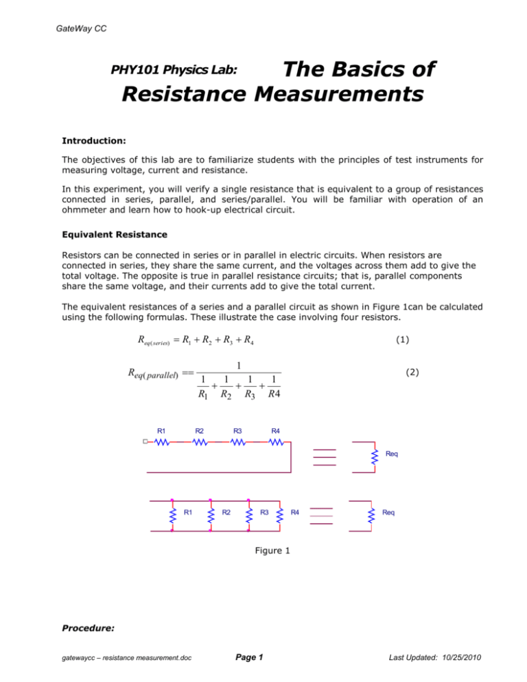
GateWay CC The Basics of Resistance Measurements PHY101 Physics Lab: Introduction: The objectives of this lab are to familiarize students with the principles of test instruments for measuring voltage, current and resistance. In this experiment, you will verify a single resistance that is equivalent to a group of resistances connected in series, parallel, and series/parallel. You will be familiar with operation of an ohmmeter and learn how to hook-up electrical circuit. Equivalent Resistance Resistors can be connected in series or in parallel in electric circuits. When resistors are connected in series, they share the same current, and the voltages across them add to give the total voltage. The opposite is true in parallel resistance circuits; that is, parallel components share the same voltage, and their currents add to give the total current. The equivalent resistances of a series and a parallel circuit as shown in Figure 1can be calculated using the following formulas. These illustrate the case involving four resistors. Req ( series) R1 R2 R3 R4 Req( parallel) R1 (1) 1 (2) 1 1 1 1 R1 R2 R3 R 4 R2 R3 R4 Req R1 R2 R3 R4 Req Figure 1 Procedure: gatewaycc – resistance measurement.doc Page 1 Last Updated: 10/25/2010 GateWay CC 1. Resistance Measurement Get the following four resistors: 10, 50, 100, and 500. Measure the resistance with the digital multimeter using the two-wire method. Record the nominal and the measured values in the table shown below. Calculate the percentage difference between the nominal and actual value. Use the given formula to calculate the % difference Measured Difference(%) Nominal Value Measured Value Measured Value Does the difference fall within the tolerance? Resistor Nominal Value () 1 10 2 50 3 100 4 500 Measured Value () Measured Difference (%) Comment 2. Resistance circuits measurements Calculate the value of the equivalent resistance for each of the circuits shown in Figures 2 and 3. Show your calculations and enter your result in the space provided. Set up each circuit as shown in the diagrams, and measure the equivalent resistance using multimeter. Please build the circuit as neat as possible. Record your measurements in the space provided. Calculate the percent error for each case. Series connections Requivalent (calculated ) = _______ Requivalent (measured ) = _______ Percent error = _______% Requivalent (calculated ) = _______ Requivalent (measured ) = _______ Percent error = _______% gatewaycc – resistance measurement.doc Page 2 Last Updated: 10/25/2010 GateWay CC Requivalent (calculated ) = _______ Requivalent (measured ) = _______ Percent error = _______% Figure 2: Series connections of resistors Parallel connections Requivalent (calculated ) = _______ Requivalent (measured ) = _______ Percent error = _______% Requivalent (calculated ) = _______ Requivalent (measured ) = _______ Percent error = _______% Requivalent (calculated ) = _______ Requivalent (measured ) = _______ Percent error = _______% Figure 3: Parallel connections of resistors gatewaycc – resistance measurement.doc Page 3 Last Updated: 10/25/2010 GateWay CC Questions 1. How many paths for current to flow in the series circuit? 2. What happens to the total resistance as you add resistors in series? Increased, decreased, stays the same? Why? 3. How many paths are there for current to flow in a parallel circuit? 4. What happens to the total resistance as you add resistors in parallel? Increased, decreased, stays the same? Why? 5. Prove this statement: The total resistance of parallel resistors is always less than that of the smallest resistor. This proof can be shown by doing the calculation for the following circuits: a. A parallel circuit with three resistors: 10 ohms, 20 ohms, and 30 ohms. The total resistance should be less the 10 ohms. b. A parallel circuit with three 100 ohms resistors and one 5 ohm resistor. The total resistance should be less the 5 ohms. 3. Measurement of resistance using the Ohm’s Law Ohm’s law states that electric current (I) through the resistor depends linearly on the voltage (V) applied across the resistor: R V I Quantity R in Ohm’s law formula is electric resistance measured in Ohm’s To verify Ohm’s law – or to measure the resistance, two quantities need to be measured: Voltage across the resistor and current through the resistor. Voltage is measured using multimeter in Volts mode. The current is measured using analog ampere-meter. The circuit used to perform these measurements is shown in figure 4. Figure 4. Ohm’s Law verification Connect the elements of the circuit using 6 V battery. Record the voltage and current reading on the chart bellow. Replace one of the two resistors with 50 , 100 , and 500 values and each time record the voltage and current data on the table. gatewaycc – resistance measurement.doc Page 4 Last Updated: 10/25/2010 GateWay CC Calculate the resistance using the Ohm’s law: Rcalc V I Calculate the absolute difference between the nominal and calculated value: Absolute Difference Nominal Value Calculated Value Calculate the percentage Difference between the nominal and calculated value: Absolute Difference Nominal Value Calculated Value 100% Calculated Value Record the Voltage and Current readings in the table bellow Resistor Nominal Calculated Value of Voltage (V) Current (A) Resistance the () Resistor() 1 10 2 50 3 100 4 500 Absolute Difference () Percentage Difference (%) . Questions: 1. Assume that you have two 100 resistors, but need 50 resistor. Is there a way to connect 100 resistors to get 50 . Explain. 2. Calculate the total resistance of three resistors connected as shown. gatewaycc – resistance measurement.doc Page 5 Last Updated: 10/25/2010


