Document 7298338
advertisement

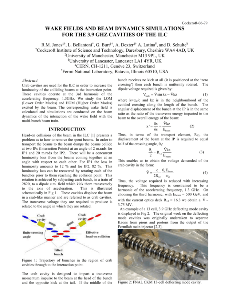
Cockcroft-06-79 WAKE FIELDS AND BEAM DYNAMICS SIMULATIONS FOR THE 3.9 GHZ CAVITIES OF THE ILC R.M. Jones‡†, L. Bellantoni*, G. Burt§†, A. Dexter§† A. Latina¥, and D. Schulte¥ † Cockcroft Institute of Science and Technology, Daresbury, Cheshire WA4 4AD, UK ‡ University of Manchester, Manchester M13 9PL, UK § University of Lancaster, Lancaster LA1 4YR, UK ¥ CERN, CH-1211, Genève 23, Switzerland * Fermi National Laboratory, Batavia, Illinois 60510, USA Abstract Crab cavities are used for the ILC in order to increase the luminosity of the colliding beams at the interaction point. These cavities operate at the 3rd harmonic of the accelerating frequency. 1.3GHz. We study the LOM (Lower Order Modes) and HOM (Higher Order Modes) excited by the beam. The corresponding wake field is calculated and simulations are conducted on the beam dynamics of the interaction of the wake field with the multi-bunch beam train. INTRODUCTION Head-on collisions of the beam in the ILC [1] presents a problem as to how to remove the spent beams. In order to transport the beams to the beam dumps the beams collide at two IPs (Interaction Points) at an angle of 2 m.rads for IP1 and 20 m.rads for IP2. There will be a concurrent luminosity loss from the beams coming together at an angle with respect to each other. For IP1 the loss in luminosity amounts to 12 % and for IP2, 82 %. This luminosity loss can be recovered by rotating each of the bunches prior to them reaching the collision point. This rotation is achieved by subjecting each bunch, in a train of 2820, to a dipole e.m. field which kick them transversely to the axis of acceleration. This is illustrated schematically in Fig 1. These cavities displace the beam in a crab-like manner and are referred to as crab cavities. The transverse voltage they are required to produce is related to the angle in which they are rotated. bunch receives no kick at all (it is positioned at the ‘zero crossing’) then each bunch is uniformly rotated. The dipole voltage required is given by: ˆ ˆ (1) Vkick Vsin kz ~ Vkz where k=d/c and kz is in the neighbourhood of the avoided crossing along the length of the bunch. The angular displacement of the bunch at the IP is in the same ratio as the ratio of the transverse energy imparted to the beam to the overall energy of the beam: ˆ x Vkz (2) x' s E beam Thus, in terms of the transport element, R12, the displacement of the beam at the IP is required to equal half of the crossing angle, c: c V̂kz (3) R12 2 Ebeam This enables us to obtain the voltage demanded of the crab cavity in the form: c c E beam V̂ (4) 2R12 d Thus, the voltage required is reduced with increasing frequency. This frequency is constrained to be a harmonic of the accelerating frequency, 1.3 GHz. On choosing the third harmonic, with Ebeam = 500 GeV, and with the current optics deck R12 = 16.3 we obtain a V̂ ~ 3.75 MV. An example of a 13 cell, 3.9 GHz deflecting mode cavity is displayed in Fig 2. The original work on the deflecting mode cavities was originally undertaken to separate Kaons from pions and protons from the output of the Fermilab main injector [2,3]. Figure 1: Trajectory of bunches in the region of crab cavities through to the interaction point. The crab cavity is designed to impart a transverse momentum impulse to the beam at the head of the bunch and the opposite kick at the tail. If the middle of the Figure 2: FNAL CKM 13-cell deflecting mode cavity. Figure 3: Eigenmodes of 9-cell crab cavity. Uppermost, the deflecting, or crabbing mode (a) at 3.9 GHz, operates with a phase change per cell. Also shown is a mode trapped (b) at 8.03 GHz . using the finite difference computer code MAFIA [5]. HOM TRANSVERSE WAKEFIELDS Two typical eigenmodes are illustrated in Fig 3. In contrast to the cavities of the main linac, the crab cavities will require damping of both the LOM and A complete set of kick factors and corresponding mode HOMs. The LOMs are monopole in character and are frequencies are illustrated in Fig. 4 for 25 bands. The mode at 3.911 GHz has the largest kick factor, by described in the next section. LOM Wakefields These are below the frequency of the deflecting mode and are restricted to the monopole passband. and are tabulated below: If they are not carefully damped then they will result in a heating of the cavity walls. (GHz) Loss factor (V/pC) 2.791995 0.00017 2.796206 0.00090 42.8034 0.00044 2.810879 0.04226 2.818909 0.00162 2.82669 1.02782 2.834273 2.53672 2.838747 0.8794 2.841427 0.00177 Table 1: Loss factors for the 1st monopole passband. calculated with MAFIA 2D. The loss factor corresponds to the energy loss per unit charge squared by a point-like bunch. Above the deflecting mode lay the HOMs and these are described in the next section. HOM Wakefields We restrict ourselves to a study of the dipole long-range HOMS. For small offset this multipole will be the dominant component. The long-range transverse wakefield [4], at a distance s behind the first bunch, is calculated from the imaginary part of the modal sum: N (1) Wt (s) 2 Im K n ein s / c en s / 2Qn c U(s) n 1 where N is the number of modes, U(t) is the unit step function, the nth mode has a quality factor of Qn, a kick factor Kn and a synchronous frequency n/2. In order to calculate the kick factors of the 9-cell cavity cavity we first calculate the eigenmodes of the system Figure 3: Kick factors for HOMs of 9-cell crab cavity. design, as this is the deflecting mode of the cavity. Over 27 bands only 14 kick factors dominate In the simulations that are described in the following section we only use these modes, summarized in table 2. (GHz) R/Q (Mm) Kt (V/pC/mm/m) 3.911 1.540 0.66844 5.153 0.019 0.00819 7.130 0.112 0.04842 7.399 0.040 0.01752 7.868 0.003 0.00112 8.031 0.126 0.05450 8.615 0.007 0.00293 8.698 0.008 0.00326 10.053 0.039 0.01709 12.978 0.019 0.00837 12.992 0.074 0.03217 13.012 0.039 0.01701 16.955 0.011 0.00486 17.534 0.016 0.00702 Table 2: Dominant HOMs of a 9-cell crab cavity. For a particular mode, we define the ratio of shunt impedance to Q: R/Q=V2/(2Ur2), where V is the voltage evaluated w.r.t the beam at a radial offset r, U is the total energy stored in the cavity and, /2 is the cavity eigenmode frequency. For a cavity of length L, the kick factor is then given by: Kt=(R/Q)(c/2L). Over the length of the bunch train, the wakefield varies rapidly and it is convenient to display the envelope of the wakefield and this is obtained from the absolute value of the modal sum (effected by taking the absolute, rather than the imaginary, component of the sum in Eq. (1)). The envelope of the wake is illustrated in Fig. 4 for the parameters given in Table 2. These parameters are supplemented with the modal Qs for the first two modes: 105 at 3.911 GHz and 104 at 5.153 GHz obtained with MAFIA simulation. For the remaining modes we assume a worst case scenario of a damping of only 10 6 for each mode. After a hundred bunches, or equivalently, approximately 10 km, the envelope of the wakefield diminishes by an order of magnitude. Furthermore, after five hundred bunches the wakefield has decayed by more than two orders of magnitude. Thus, in simulations between 200 and 500 bunches will be required to adequately describe the beam dynamics. beam and only the other modes were detuned. There are resonances when the bunch spacing deviates from the design value, e.g..at -0.016% or 0.0045% For the present wake fields the emittance dilution can reach up to 100 % in the worst case.. The multi-bunch emittance will be reduced by intra-train feedback using the FONT [8] facility under development for the ILC, but more detailed investigation is clearly needed. We therefore also estimate the average single bunch emittance growth and find approximately 1.5% for -0.016% detuning, the worst multi-bunch case. The multi-bunch emittance growth is mainly due to varying offsets along the train, see Fig. 5. The impact of the single bunch emittance growth on the luminosity remains to be studied, but could potentially be severe due to the banana effect [9]. Fig ure 5: Beam offset at IP due to the crab cavity wakefields along the train for incoming beam angle of. y’. CONCLUSIONS Figure 4: Envelope of the transverse wake in units of W 0 (=1.78 V/pC/mm/m) for a 9-cell cavity. The wake at the location of each bunch is indicated by the red points. BEAM DYNAMICS In order to determine the importance of the crab cavities with respect to the beam dynamics we perform some preliminary studies with the computer code PLACET [6]; more detailed studies will follow at a later stage. We track the beam through 4 cavities under the influence of the 14 dominant modes delineated in the previous section. We focus on the 20 mrad crossing angle at the IP. The multibunch emittance dilution at the IP is simulated for a beam that enters the BDS with a vertical position and angle error that is equal to the RMS beam size. In order to assess the influence of systematic errors in the mode frequencies on the beam dynamics we make several simulations in which the mode frequencies are slightly varied; the emittance growth is found to be quite proportional to SRMS [7]. This preliminary set of simulations shows that the multi-bunch emittance increase can grow up to 500% in the worst case. In the horizontal plane it should be possible to control the detuning of the first mode quite well. To simulate this, the frequency of the first mode was set to a value that does not affect the The dependence of the emittance growth on the frequencies of the transverse modes is not negligible. Further study is needed to determine the luminosity loss associated with a bad set of transverse frequencies, including single and multi-bunch effects. Additional studies will be made on the accuracy of the mode frequency calculations. Although a recent set of bead-pull experiments confirm the frequency predictions reasonable well [11]. Finally we note, that the behaviour of the emittance dilution for incremental changes in the bunch spacing, is in general, well predicted by the RMS of the sum wakefield. ACKNOWLEDGEMENTS We are pleased to acknowledge useful discussions and encouragement in this work from A. Seryi . REFERENCES [1] http://www.linearcollider.org. [2] D.A. Edwards, Editor,1998, Fermilab TM-2060. [3] M. McAshan and R. Wanzenberg, 2001, Fermilab TM-2144. [4] P.B. Wilson, 1989, SLAC-PUB-4547. [5] The MAFIA Collaboration, CST, Darmstadt, 1994. [6] D. Schulte, CLIC-Note 437, 2000. [7] R.M. Jones et. al, 1999, SLAC-PUB-8101. [8] P.N. Burrows et. al, 2005, SLAC-PUB-11760 [9] R. Brinkmann, O. Napoly, D. Schulte DESY-TESLA2001-16 [10] P. Goudket, 2006, private communication.


