PerformanceModel_Keegan
advertisement
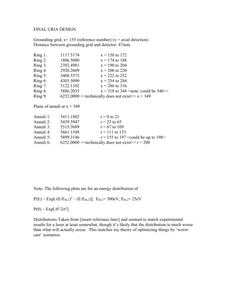
FINAL CRIA DESIGN Grounding grid, x= 155 (reference number) (x = axial direction) Distance between grounding grid and detector: 47mm. Ring 1: Ring 2: Ring 3: Ring 4: Ring 5: Ring 6: Ring 7: Ring 8: Ring 9: 1117.5174 x = 158 to 172 1806.5000 x = 174 to 188 2392.4981 x = 190 to 204 2920.2609 x = 206 to 220 3408.5573 x = 222 to 252 4303.5090 x = 254 to 284 5122.1102 x = 286 to 316 5886.2035 x = 318 to 344 <note: could be 346>> 6252.0000 <<technically does not exist>> x = 349 Plane of annuli at x = 349 Annuli 1: Annuli 2: Annuli 3: Annuli 4: Annuli 5: Annuli 6: 5411.1802 r = 0 to 21 5439.5947 r = 23 to 65 5515.3689 r = 67 to 109 5661.1548 r = 111 to 153 5899.3146 r = 155 to 197 <could be up to 198> 6252.0000 <<technically does not exist>> r = 200 Note: The following plots are for an energy distribution of P(E) ~ Exp[-(E/Eth,1)2 – (E/Eth,2)]; Eth,1= 300eV, Eth,2= 25eV P(θ) ~ Exp[-θ2/2σ2] Distributions Taken from [insert reference later] and seemed to match experimental results for a laser at least somewhat, though it’s likely that the distribution is much worse than what will actually occur. This matches my theory of optimizing things by ‘worstcast’ scenarios. Relative Voltage Relative Voltage vs. Time, for m = 1, impact radius of 120mm 1 0.9 0.8 0.7 0.6 0.5 0.4 0.3 0.2 0.1 0 0.845 0.85 0.855 0.86 0.865 0.87 Time of Flight (usec) Relative Voltage Relative Voltage vs. Time, for m = 30, impact radius of 120mm 1 0.9 0.8 0.7 0.6 0.5 0.4 0.3 0.2 0.1 0 4.64 4.66 4.68 4.7 4.72 Time of Flight (usec) 4.74 4.76 4.78 Relative Voltage Relative Voltage vs. Time, m = 100, impact radius of 120mm 1 0.9 0.8 0.7 0.6 0.5 0.4 0.3 0.2 0.1 0 8.45 8.5 8.55 8.6 8.65 8.7 8.75 Time of Flight Mass Resolution Mass Resolution vs. Impact Radius, 'worst-case ions' up to 50eV 200 180 160 140 120 100 80 60 40 20 0 0 50 100 150 200 Impact Radius (mm) Note: worst case ions P(E) = const, up to 50eV. Isometric angular spread. The following are Contour plots that show the radius at which an ion hits a detector given an initial energy and angle for a variety of impact positions. Note that for impact radii less than 130mm, zero-energy ions WILL NOT HIT a detector smaller than 10mm in radius. This isn’t a huge problem, because the device is optimized for impacts between 130 and 170mm of radius. However, this gives me concerns about a small ion detector. Ion Detection Radius vs. Initial Ion Energy and Angle, for Im pact Radius = 90m m S25 S22 S19 S16 70 30 -10 -50 -90 S13 Initial Ion Angle (-90 = radially in. 0 = axial. +90 = radially out) Ion Energy (eV) 60-70 50-60 S10 40-50 S7 30-40 S4 20-30 0 10-20 0-10 Ion Detection Radius vs. Initial Ion Energy and Angle, for Impact Radius = 110mm 50 60-70 Ion Energy (eV) 50-60 40-50 30-40 20-30 10-20 0-10 -90 -30 0 90 30 Initial Ion Angle (-90 = radially in. 0 = axial. +90 = radially out) Ion Detection Radius vs. Initial Ion Energy and Angle, for Impact Radius = 130mm 50 Ion Energy (eV) 40-50 30-40 20-30 10-20 0-10 -90 -30 30 0 90 Initial Ion Angle (-90 = radially in. 0 = axial. +90 = radially out) Ion Detection Radius vs. Initial Ion Angle and Energy, for Impact Radius r = 150mm 50 Initial Ion Energy 30-40 20-30 10-20 0-10 -90 -30 0 90 30 Initial Ion Angle (-90 = radially in. 0 = axial. +90 = radially out) Ion Detection Radius vs. Initial Ion Energy and Angle, for Impact Radius = 170mm 50 Ion Energy (eV) 40-50 30-40 20-30 10-20 0-10 -90 -30 30 0 90 Initial Ion Angle (-90 = radially in. 0 = axial. +90 = radially out) Percentage of Ions Collected Percentage of Ions Collected vs. Detector Radius. For y = 120 mm 100 90 80 70 60 50 40 30 20 10 0 0 5 10 15 20 25 30 35 40 45 50 55 60 65 70 75 80 85 Radius of Ion Detector (mm) The apparent time resolution does not change (for impact radius = 120mm) for detectors of radius > 5 mm. To compare the 1mm vs. the 2mm gap versions. Comparison of CRIA Voltage Models with 1mm and 2mm Gaps 400 350 Time Resolution 300 250 1mm Gaps 2mm Gaps 200 150 100 50 0 0 50 100 150 200 Impact Radius Note: this is not a strict comparison, because I intentionally tried to get better performance for large impact radii for the 2mm gap design, at the (slight) expense of smaller impact radii. FOR 1mm GAPS the design *would be* Grounding grid, x= 155 Distance between grounding grid and detector: 47mm. Ring 1: Ring 2: Ring 3: Ring 4: Ring 5: Ring 6: Ring 7: Ring 8: Ring 9: 1118.2516 x = 157 to 172 1806.2954 x = 173 to 188 2391.1490 x = 189 to 204 2917.6823 x = 205 to 220 3404.7034 x = 221 to 252 4297.0360 x = 253 to 284 5112.9789 x = 285 to 316 5876.4002 x = 317 to 348 6238.0000 <<technically does not exist>> x = 349 Plane of annuli at x = 349 Annuli 1: 5389.5613 r = 0 to 21 Annuli 2: 5419.0092 r = 22 to 65 Annuli 3: 5496.5850 r = 66 to 109 Annuli 4: 5644.5936 r = 110 to 153 Annuli 5: 5884.5893 r = 156 to 199 Annuli 6: 6252.0000 <<technically does not exist>> r = 200


