Design Plan Checklis..
advertisement
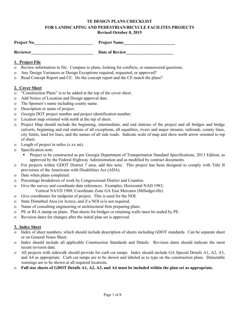
TE DESIGN PLANS CHECKLIST FOR LANDSCAPING AND PEDESTRIAN/BICYCLE FACILITES PROJECTS Revised October 8, 2015 Project No.___________________________ Project Name________________________ Reviewer_____________________________ Date of Review______________________ 1. Project File Review information in file. Compare to plans, looking for conflicts, or unanswered questions. Any Design Variances or Design Exceptions required, requested, or approved? Read Concept Report and CE. Do the concept report and the CE match the plans? 2. Cover Sheet “Construction Plans” is to be added at the top of the cover sheet. Add Notice of Location and Design approval date. The Sponsor’s name including county name. Description or name of project. Georgia DOT project number and project identification number. Location map oriented with north at the top of sheet. Project Map should include the beginning, intermediate, and end stations of the project and all bridges and bridge culverts, beginning and end stations of all exceptions, all equalities, rivers and major streams, railroads, county lines, city limits, land lot lines, and the names of all side roads. Indicate scale of map and show north arrow oriented to top of sheet. Length of project in miles (x.xx mi). Specification note: Project to be constructed as per Georgia Department of Transportation Standard Specifications, 2013 Edition, as approved by the Federal Highway Administration and as modified by contract documents. For projects within GDOT District 7 area, add this note: This project has been designed to comply with Title II provisions of the Americans with Disabilities Act (ADA). Date when plans completed. Percentage breakdown of work by Congressional District and Counties. Give the survey and coordinate data references. Examples, Horizontal NAD 1983; Vertical NAVD 1988; Coordinate Zone GA East Mercator (Milledgeville) Give coordinates for midpoint of project. This is used for the NOI. State Disturbed Area (in Acres), and if a NOI is/is not required. Name of consulting engineering or architectural firm preparing plans. PE or RLA stamp on plans. Plan sheets for bridges or retaining walls must be sealed by PE. Revision dates for changes after the initial plan set is approved. 3. Index Sheet Index of sheet numbers, which should include description of sheets including GDOT standards. Can be separate sheet or on General Notes Sheet. Index should include all applicable Construction Standards and Details. Revision dates should indicate the most recent revision date. All projects with sidewalk should provide for curb cut ramps. Index should include GA Special Details A1, A2, A3, and A4 as appropriate. Curb cut ramps are to be shown and labeled as to type on the construction plans. Detectable warnings are to be shown at all required locations. Full size sheets of GDOT Details A1, A2, A3, and A4 must be included within the plan set as appropriate. Page 1 of 8 4. Revision Summary Sheet Revision summary sheet has been included giving date of revision, sheet number of revised sheet, and description of revision. 5. General Notes/Project Notes One-Call Logo for Utilities Locations 811. List utility and railroad owners and contact information. Add the Environmental Resource Impacts Table to this sheet. (see example at end of document for more information) This chart will include: Resource name (wetlands 1, stream 1, historic site 1, TE species) and should match the environmental document. Resource location (station or station range) Construction Activity (roadway widening, creek realignment) Permitted Activity (No 404 permit required, not in project limits, linear feet of stream impacted, area of wetland impacted) Controlling Criteria (if applicable) Special Provision? (yes or no) Comments included in permit (special restrictions or permit expiration date) It should also include any inspections that are mandated on the green sheet. If no impacts exist state “no impact” or N/A Verify that the General Notes do not conflict with anything else in the plans. Check that project specific notes do not conflict with other contract documents. Add Traffic Control note, if appropriate: The contractor will be responsible for preparing a traffic control plan showing the proposed measures to manage traffic during construction activities. The plan shall conform to the 2009 Manual of Uniform Traffic Control Devices and Georgia DOT Specification 150. Any lane closures must be approved by and coordinated with the Georgia DOT Area Engineer. Lane closures will require proper lane tapers and advance warnings per Georgia DOT standards. Add Traffic Signing Note, if appropriate: All signing, marking, and traffic control shall conform to the Manual on Uniform Traffic Control Devices, 2009 Edition. Add Traffic Signal Note, if appropriate: Existing traffic signals shall remain operable at all times. Contact _________, GDOT Signal Engineer (or city contact as appropriate), at ____________ prior to beginning work to discuss buried signal equipment. When using the GDOT Specification 702 add this note: Review length of maintenance requirements – two growing seasons – in the 702 specification. List any time restrictions on lane closures, e.g., before 9 AM and after 4 PM. 6. Typical Sections Typical Sections are to be drawn from ROW limit to ROW limit with all existing and proposed features labeled. It is especially important to clearly indicate the proposed work. Label lanes by type and width; proposed pavement type and thickness; maximum cross slopes and direction for sidewalks and multi-use trails; offsets of trees and poles; and dimensions of other items, such as offsets for existing and proposed utility and pedestrian light poles. Offsets for trees are shown as from face of curb to center of tree. Offsets for utility poles are shown from face of curb to face of pole. Offsets for pedestrian light poles are shown from face of curb to face of pole base. These offsets are used to determine if a design exception or design variance is needed. Lane widths, shoulder widths, curb and gutter widths, landscape area width, sidewalk, or trail widths. Check lane widths, shoulder widths, speed design, etc. against GDOT Design Policy Manual. Check horizontal offset requirements. If bridges are included, check sidewalk or trail width versus bridge clear width. The cross slope of multiuse trails should be uniform; no crown section. Typical Sections should indicate rate and direction of cross slopes for paving, shoulders, sidewalk, trail, and bridges. Give station range for each typical section. Identify asphalt and concrete paving and thickness. Add Superpave Mix Design Level. Use metric Superpave nomenclature for all asphalt paving, e.g., 9.5 mm Superpave, 12.5 mm Superpave. Page 2 of 8 Typical Sections should show stationing applicable to each section. Stationing should not overlap or skip. Superelevated sections should be shown where applicable. Each pavement layer should be labeled with a depth and type of material. On widening and reconstruction projects typical sections should indicate rate of slope or “Match Existing Slope”. Check front slopes, ditch depths, overall dimensions, etc. If there is a sidewalk with no curb, the sidewalk is to be at least 5 feet from the nearest travel lane. Curb and Gutter sections should be labeled with the type and size. Curb and gutter on the high side of superelevated section should spill with the same direction and slope as roadway. Check all notes and details for accuracy and need. 7. Summary of Quantities Sheet List all construction items and quantities to be paid for by the project contract. Make separate summaries by funding source for projects having more than one source of funds, e.g., TE, HPP, STP, LCI, etc., or when there are costs not eligible for federal funding identified at the beginning of the project construction. Summarize as described in GDOT Plan Presentation Guide Section 06. Use the bid item number, description of item, and unit of measure from the GDOT Bid Item index. Any item that does not have a current pay item number in the current GDOT Pay Item Index, a pay item number can be created. This number can be any number as long as it is not a number in the current pay item index. The prefix will come from the section of the Standard Specifications that this item applies, e.g., SEC 702 VINE, SHRUB and TREE PLANTING. Add a description that describes the created item as follows: 702-0030 Acer Rubrum. In addition, a Special Provision will need to be developed for the created pay item to indicate what material and installation work is to be performed by the contractor in return for payment of the bid cost of the item. Grading Complete – Add this pay item to the Summary. This will cover any miscellaneous earthwork and minor grading that may be needed for this project. Any removals should be noted in the plans stating that items to be removed are to be included in the price bid for “Grading Complete”. The unit and quantity for all LUMP SUM items is LUMP SUM not one (1). Maintenance of Silt Fence is 50% of the total quantity for the silt fence. For example, if there are 680 linear feet of silt fence, then the quantity for maintenance of silt fence is 340 linear feet (680 feet x 50%). The total number of proposed handicap ramps can be identified under pay item number 005-0023 ADA Ramps with a unit of measure of EACH. The cost of the ramps can also be included as part of the concrete sidewalk pay item as noted in GDOT Detail A3, Note 6. Check if signs are going to be relocated. If so should have pay item 610-6515 Remove Hwy Signs & 611-5360, Reset Hwy Signs. Relocated signs are to meet current GDOT requirements, such as sheeting, post, offsets, etc. If new sign panels are required, set up appropriate pay items. Verify that the correct pay items have been included. 8. Construction Plan Sheets All Environmentally Sensitive Area (ESA) flags on plan sheets shall be changed to read "ESA - See Environmental Resources Impact Table in General Notes for construction restrictions." The ESA notes shall be placed on ALL plan sheets where an ESA exists. Check for Begin Project and End Project stationing. Check side road limits as well. All transitions and proposed construction must be within the project limits. No catch basins should be constructed within radii limits of intersections. Shift catch basins out of radii or use 1019A, Type E, modified or 1019B. Check spacing and size on all drainage structures. Are pipe sizes, direction of flow and structure numbers shown on plan sheets? Check all equalities and exceptions for stationing, grade continuity, and horizontal continuity. Check for locations where Type 3 backfill material is required. Also, check for locations where Type 2 backfill material is normally used, such as live streams or unsuitable conditions. Check that the following items are plotted on the plan sheets: Survey Centerline, Construction Centerline, Existing Right of Way, Required Right of Way and Easements with Stations and Offsets at break points, Construction Limits, Property Lines and Owner’s Names, North Arrows, Stationing, Existing Topography, Ditches, Drainage Structures, Flow Lines, Curb and Gutter, Sidewalks, and Curb Ramps. Page 3 of 8 When sidewalks cross driveways, assure that there is a pedestrian access route at least 48” wide with a 2% maximum cross slope. Use GDOT Detail A1 or reconstruct portion of driveway to provide such a crossing. Reconstruction of driveway will require a driveway profile in plans. Review grades for trails and sidewalks not adjacent to a roadway to assure grades are acceptable. 9. Drainage Profiles/Drainage Cross Sections Will Type 2 or 3 backfill material be required? Check drainage summary, plan and profile sheets, and drainage cross sections. Normally Type 2 backfill for pipes will be used only for live streams or unstable conditions. Check for pipe end treatment (flared end section, safety end section, headwalls, etc.). Use outlet headwall where velocities are excessive. See drainage manual. Drainage cross sections should be checked against drainage summary and plan and profile sheets. Make sure there is no conflicting information. Drainage cross sections should show height of fill, which will determine class of pipe or design of culvert, and size, station and skew of structure. 10. Utility Plans Show existing, proposed, and adjusted utility locations. Check utility sheets and cross section sheets with plan and profile sheets for possible conflicts with proposed construction. 11. Lighting Plans Lighting items are to have a separate Summary of Quantities sheet. Plans are to include all details needed for the lighting system. Check to determine if a design exception or design variance is needed or has been approved for placement of light poles Check to see that this information does not conflict with anything in the contract documents. Projects having five or more pedestrian lights need the photometrics and lighting plans reviewed and approved by the GDOT Lighting Group in General Office. 12. Signing and Marking and Signal Plans Are there traffic signals at the intersections? If yes, pedestrian signal heads, crosswalk markings, and curb cut ramps must be provided. If the signal is owned and operated by GDOT, contact the District Traffic Signal Engineer to determine if a revised signal permit is required. If a revised signal permit is required, the Sponsor’s design consultant is to contact directly the District Traffic Signal Engineer. The plans should not be approved until the revised or new signal permit is approved by GDOT. Are signal plans required? If so, have they been included? The GDOT District Traffic Operations Office will review and approve the traffic signal plans. Are all strain pole locations shown for overhead signs and signals? Do the locations affect sidewalk clearances? Do any proposed islands shown on the signing and marking plans match those shown on the construction plans? (Concrete/Striped) Are pay items set up for all striping items? Striping for bike lanes and trails is to be paint. Other markings may be thermoplastic. Show type, color, and width. Use the GDOT standard crosswalk marking details for all crosswalks. If the crosswalk has an architectural treatment, there shall be an 8” white stripe parallel to the crosswalk on each side of the crosswalk. Pedestrian and Bicycle warning signs shall be fluorescent yellow-green in color using Type 11 wide-angle prismatic sheeting. The sign sizes shall be: W11-1 & W11-2 = 36” x 36”; W16-7p = 30” x 18”; W16-9p = 36” x 20” Red series signs and warning signs shall be Type 11 sheeting. The plans are to show the legend, color scheme, size, and sheeting requirements for all signs. See GDOT Signing and Marking Guidelines Edition 3.0 for requirements. Relocated signs are to meet current GDOT requirements, such as sheeting, post, offsets, etc. If new sign panels are required, set up appropriate pay items. Use GDOT T-3a Square Sign Post Detail for post design. Page 4 of 8 If marked crosswalks are in the plans, they are to be provided in accordance with GDOT Signing and Marking Guidelines, version 3.0, Section 12.4, Guidance on Marking Crosswalks. Ask designer for documentation giving the reasons for providing marked crosswalks as outlined in the Crosswalk Guidance. Use pavement marking materials specified by GDOT Signing and Marking Design Guidelines, version 3.0, Section 12.1.1. Add edge lines in curb and gutter sections per GDOT Signing and Marking Design Guidelines, version 3.0, Section 12.2.1. 13. Landscaping plans Show all existing permitted billboards within 500 feet of the right of way along all State Routes. If a billboard exists within 500 feet of the proposed landscape, plant material that will grow to obstruct the visibility of the billboard within the 500-foot view zone of the billboard sign face cannot be planted. Plant specifications – GDOT Special Provision 702 includes plant specifications if not shown on the plans. Pruning specifications – Limb to at least 80 inches per ADAAG 307.4. Planting details – GDOT Special Provision 702 includes planting details but such details are usually also shown on the design plans. Tree protection – Specify if protection for existing trees is appropriate. Planting plans Location of plants Types of plants, by key reference or plant name Check plants with exotic/invasive species plant list. Check sight triangles at intersections. No plants over 30” mature height for plants within sight distance triangle. Check offset of trees with GDOT Design Policy Manual Table 5.3. Irrigation Sponsor is to sign indemnity agreement with GDOT if project within GDOT right-of-way. Use pop-up heads only Controller box must be located off GDOT right-of-way. Valve boxes need to be locked or located off the GDOT right-of-way. Add tracer wire to all piping. Add a shut-off valve at the water meter for emergency purposes. 14. Wall Plans Are all walls shown and labeled on plan sheets? Provide top and bottom elevations and stationing for walls. Retaining walls – submit design calculations if not using Georgia Standard 9031L. GDOT Office of Bridge and Structures will review plans for walls having a special design exceeding 5’ in height. Information to be sent is to include the wall envelope and design calculations sealed by a P.E. Structural. If the wall design uses 9031L or has a standard design then the design need not be sent to the Office of Bridge and Structures. Make all submittals to Moreland Altobelli and Associates we will route the documents through Office of Bridge and Structures. 15. Bridge Plans All pedestrian overpass structures should be designed in accordance with the AASHTO LRFD Guide Specifications for Design of Pedestrian Bridges, 2nd Edition, 2009. The vertical clearance over roadways shall be a minimum of 17’-6”. For horizontal clearances, the intermediate bents shall be located so as to provide the desirable clear zone as specified in the AASHTO Roadside Design Guide whenever practical. Where this is not practical, the designer shall coordinate with the Project Manager to determine how to protect the columns from traffic. The design loadings must be on the plan sheets. See AASHTO specifications for pedestrian bridges. Submit Bridge Foundation Report (BFI) and hydrology report, if applicable, with plans. Are all bridges shown and labeled on plan sheets? Is inside clear bridge width at least the width of the paved trail or sidewalk width? Does bridge alignment match roadway alignment, both horizontally and vertically? Page 5 of 8 Highwaters should be shown in accordance with the drainage manual. Geometric Design Standards must be met. Make all submittals to Moreland Altobelli and Associates (MAAI). MAAI will route the documents through Office of Bridge and Structures. 16. Erosion, Sedimentation, and Pollution Control Plans The ESPCP is to be submitted to the Local Issuing Authority or the Environmental Protection Division, as appropriate, for review and approval. If the project disturbed area is less than 1 acre the following applies: Include BMP Location plan sheets. Include All 6 Erosion Control Legend and Uniform Code Sheets (must be listed in the index with revision date) Include BMP construction standards and details (must be listed in the index with revision date) If the project disturbed area is 1 acre or more the following applies: Must be separate set of erosion control plans located at the back of the complete set of plans. A separate cover sheet, all certification notes, signed and sealed by a design professional. State disturbed area and that a NOI is required, on cover sheet. Include completed erosion control plan checklist within the plans. Include Erosion, Sediment and Pollution Control Plan (ESPCP) General Notes. For TE projects the designer is responsible for the 7-day inspection. The Primary Permitee is responsible for obtaining the services of the ESPCP designer to conduct the inspection. There is a standard GDOT ESPCP note that makes the GDOT Construction Project Engineer responsible for the 7-day inspection. That note does not apply to TE projects because the projects are let to contract by the Sponsor and not by GDOT. Include Drainage Area Map Show BMP Location plan sheets for each stage of construction. (all three phases must be shown) Include Watershed Map and Site Monitoring Location Include All 6 Erosion Control Legend and Uniform Code Sheets (must be listed in the index with revision date) Include BMP construction standards and details (must be listed in the index with revision date) 17. Georgia Water Quality Control Act and Federal Clean Water Act A. Projects affecting storm sewer systems owned by GDOT in a MS4 permitted area are required to comply with Section 4.2.5.1a of the NPDES MS4 Permit. Section 4.2.5.1a of the permit requires design of storm water structures at outfall locations that provide: 1) Removal of 80% of total suspended solids (TSS) from the first 1.2-inches of rainfall; 2) 24-hour extended detention storage for the 1 year 24 hour storm event; 3) Match pre-developed flow rates for the 25 year 24 hour storm event; and 4) Control the 100 year 24 hour storm event. - The design and ESPC plans are to include appropriate Best Management Practices outlined in the permit unless use of such BMPs is infeasible in accordance with paragraph 4.2.5.1(b) of the permit. An appropriate infeasibility letter is to be prepared by the designer and submitted to the project PM for action. - The GDOT MS4 permit GAR041000 is available at: http://mydocs.dot.ga.gov/info/designbuild/Shared%20Documents/232310/MS4%20Permit/Final_DOT_SW_NPDES_Permit_MS4_Dec_2011.pdf B. For projects affecting separate storm sewer systems owned by local governments (not on a U.S./state route), the designer is to contact the jurisdiction owning the MS4 facility for applicable requirements for the design and ESPC plans. 18. General Comments/Things to Look For Contact the local issuing authority for local requirements, land disturbance permits, NPDES, Water quality, MS4 etc.. All plans are to be in English units. On all projects, check the overhead clearance under bridges. The clearance should be 10 feet; 8 foot minimum (see AASHTO Pedestrian Facilities Guide pg 98). On cross sections for facilities under bridges, give the elevations for the trail or sidewalk and the bottom of the bridge beam. This information is used to confirm the overhead clearance. For sidewalks along a roadway without a curb the recommended offset is 5 feet the minimum offset is 2 feet from nearest travel lane, see GDOT Pedestrian & Streetscape Guide, page 92. Page 6 of 8 The placement of the handicap parking spaces is to be shown on the plans. When placing the handicap spaces for angle or perpendicular parking, the access aisle is to be 8 feet wide. The access aisle needs to be accessible to the sidewalk typically through the use of a curb cut ramp that cannot occupy any of the access aisle area. For parallel parking, the handicap space should be placed at the end of the block so the user can access the curb cut ramp for the crosswalk. Label all curb cut ramps using type as shown on GDOT Detail A3. Show detectable warnings on those ramps having detectable warnings. No parking spaces within 20 feet of a crosswalk as specified in Georgia Motor Vehicle Code 40-6-203. No parking spaces within 30 feet of a flashing signal, stop sign, yield sign, or traffic control signal as specified in Georgia Motor Vehicle Code 40-6-203. Plans should include method of connection when extending pipe not in kind or when extended in a different grade or slope. (concrete collars, etc.) See GDOT Standard 9031U. The installation of sidewalks and landscaping can be done on easements. Cut and Fill slopes, channels and ditches may be constructed on easements. Superpave mixes: Type B mix is now 19mm Superpave, Recycled Asphaltic Concrete, GP1 or 2, Item 402-3190. Type H mix is now 12.5mm Superpave, Recycled Asphaltic Concrete, GP2, Item 402-3130. Type E mix is now 12.5mm Superpave, Recycled Asphaltic Concrete, GP2, Item 402-3130. Type F mix is now 9.5mm Superpave, Recycled Asphaltic Concrete, GP2, Item 402-3131. Thickness of each pavement layer is given in terms of a spread rate of 1” = 110 lb/sy. For example, a 2” layer has a spread rate of 220 lb/sy. Proprietary Items – Items that are specifically identified as one brand and model only, such as Toro irrigation, Boral Brick, or certain pedestrian light poles are considered proprietary. Proprietary items must be approved by FHWA for use. If three (3) or more brand and model numbers are listed along with the statement “or approved equal”, the items are not considered proprietary. Check for such an approval letter in our files or initiate the process to have the Sponsor make such a request. GDOT Standard 9031R for handrails, if used for stairs and ramps, does not meet ADAAG requirements for extension beyond the last riser (12” plus one tread width for stairs and 12” for ramps) and height of handrail (34-38”). Example of Environmental Resource Impact Table: Environmental Resources Impact Table Resource Name (from Section A of the ECT) Downtown Historic Commercial District (ESA 1) Protected Species Perennial Stream 1 (PS 1) Perennial Stream 1 Buffer (ESA 2) These resources and the restrictions listed are governed by state and federal law. Permitted Special Location Construction Comments Provision Activity (from Beginning Ending (from Section A of (from Section C of the ECT, Side Section B of STA STA the ECT) comments only) the ECT) Historic granite District name and ESA 1 curbing shall be Lt & delineated in plan views. 0+00 100+00 maintained to N/A Rt HPD 50% and 100% site visits maximum extent required. possible. Bridge construction, For the protection of Indiana, Lt & bridge piling such SP 0+00 100+00 Gray, & Northern Long-eared Rt that harm to listed 107.23.G bats. species is avoided. Stream centerline, name, and PS1 delineated in plan views. 25 ft/0.01 ac of Double Row silt fence and hay 15+00 16+00 Left N/A riprap impact bales shall be placed at the construction limits along the stream buffer. Bridge Buffer and ESA 2 delineated in 15+00 16+00 Left N/A construction, plan views. Page 7 of 8 bridge piling None (This row is an example of a project with no resources.) None None None None None None 404 Permits and Variances (from Section D of the ECT) Expiration dates (if applicable) Contact GDOT OES 6 months prior to expiration, if work will extend beyond this date. Stream Buffer Variance mm/dd/yyyy 404 mm/dd/yyyy 50% Construction Complete Historic Preservation Division (HPD) Site Visit 100% Construction Complete Historic Preservation Division (HPD) Site Visit Page 8 of 8

