Utility Systems Technologies, Inc.
P.O. Box 110
Latham, NY 12110
SagFighter™ Active
Voltage Conditioner / Sag
Ride Through (SRT)
Overview
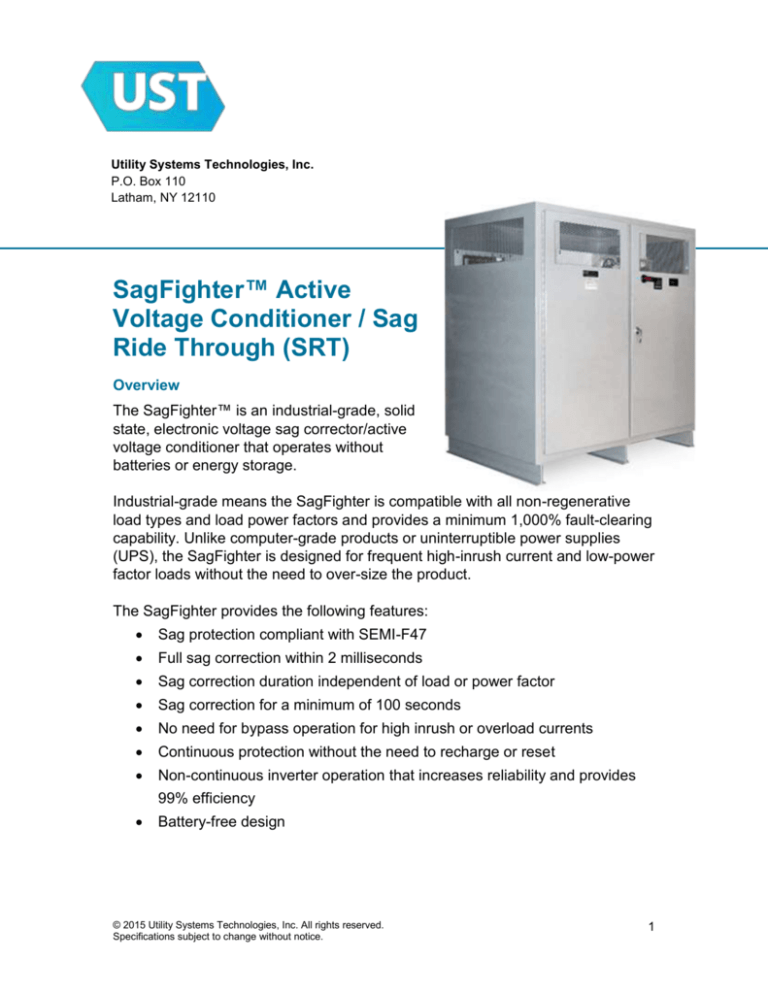
The SagFighter™ is an industrial-grade, solid
state, electronic voltage sag corrector/active
voltage conditioner that operates without
batteries or energy storage.
Industrial-grade means the SagFighter is compatible with all non-regenerative
load types and load power factors and provides a minimum 1,000% fault-clearing
capability. Unlike computer-grade products or uninterruptible power supplies
(UPS), the SagFighter is designed for frequent high-inrush current and low-power
factor loads without the need to over-size the product.
The SagFighter provides the following features:
Sag protection compliant with SEMI-F47
Full sag correction within 2 milliseconds
Sag correction duration independent of load or power factor
Sag correction for a minimum of 100 seconds
No need for bypass operation for high inrush or overload currents
Continuous protection without the need to recharge or reset
Non-continuous inverter operation that increases reliability and provides
99% efficiency
Battery-free design
© 2015 Utility Systems Technologies, Inc. All rights reserved.
Specifications subject to change without notice.
1
The SagFighter consists of a three-phase transformer with each of its secondary
windings connected in series between the source (incoming line) and the load(s).
Load current flows through the secondary windings of the transformer while the
unit operates in a “monitoring” mode with the primary transformer windings
shorted through SRC switches.
The SagFighter™ continuously monitors the input voltage waveform for any
deviation from a balanced, three-phase voltage. Upon sensing a deviation, the
Sag Fighter engages an inverter circuit to apply an injection voltage to the
primary windings of the series-connected transformer. The injection voltage is
synthesized with a magnitude, shape, and phase angle so that when it is added
in series with the incoming voltage, a balanced, three-phase voltage results.
When normal, three-phase incoming voltage is detected at the SagFighter input,
the inverter circuit is disengaged and the unit returns to monitoring mode.
The SagFighter is thermally ranged to provide continuous correction for a voltage
sag, although this is not normally required.
The SagFighter uses natural convection cooling and has no fans or other moving
parts. Larger units may include heat-sink fans that operate only when the unit is
correcting a sag event. An automatic electronic failsafe bypass is incorporated
into the standard design so the SagFighter maintains power to the load if a unit
malfunctions.
The SagFighter automatically corrects voltage sags with no operator or
programming required. The unit display provides unit status and historical
information on sag correction events. Alarm contacts are also provided to permit
remote indication of SagFighter status.
SagFighter installation is simple. The unit arrives completely assembled and
requires no programming, testing, measuring or setting of switches. It is designed
to install much like a dry-type transformer: simply place the unit and make input
and output wiring connections. The SagFighter typically has no maintenance
schedule other than routine inspection and cleaning.
© 2015 Utility Systems Technologies, Inc. All rights reserved.
Specifications subject to change without notice.
2
SagFighter™
Specifications
Application
Power Rating/Size (kVA)
100, 125, 150, 200, 250, 300, 350, 400, 500, 750, 1,000, 1,250, 1,500,
1,750, 2,000 kVA
Phase - Frequency (Hz)
Standard Input/Output Voltages
3Ø, 50 or 60 Hz
60 Hz: 208, 240, 480, 600 50 Hz: 220, 380, 400, 415
(non-standard voltages available)
Sag Correction/Operating Characteristics
Sag Correction
Output Regulation
1- or 2-phase sags to 30% remaining voltage (-70% sag) corrected to at least 95% of
nominal voltage. 3-phase sags to 60% remaining voltage (-40% sag) corrected to at least
95% of nominal voltage.
Nominal voltage ±5% during sag correction [Note: unit normally operates in monitoring
mode until voltage reaches 90% of nominal voltage, at which time sag correction is initiated]
Response Time
Full sag correction typically within 2ms, regardless of load or load power factor.
Correction Duration
Sags corrected for a minimum of 100 seconds, regardless of load or power factor.
Regulation Variation
None: regulation constant for 0 to 100% load and any load power factor.
Phase Shift Correction
Phase shifts are corrected automatically during sag correction.
Harmonic Distortion
None: added in monitoring mode.
Overload/Inrush Capability
1,000 % - 1 second, 500% - 5 seconds, 200% - 1 min.; 1,000% fault clearing
Load / Power Factor
No minimum or part load or load-power factor limitations; compatible with all load types.
Efficiency
99% typical
Operating Frequency
+/- 3% from nominal frequency (50Hz or 60Hz)
Performance specifications are based on the input (source) voltage meeting IEEE 519
standards.
Operating Environment
Noise Suppression/Load Protection
Surge Suppression
Included, complies with ANSI/IEEE C62.41, UL 1449
Input Circuit Breaker
Included, standard, UL 489, ANSI/IEEE C22.2
Failsafe Electronic Bypass
Auto-actuation on high temperature, over-current, component failure with no loss of load
Construction
Technology
Microprocessor-controlled, inverter-based series voltage injection
Transformer
Copper-wound, dry-type series transformer (3W+G input and output)
Inverter Operation
Enclosure
Non-continuous operation – only during sag correction
Natural convection cooled with heat-sink fans used only during sag correction [contaminant
free, dry, clean air]
Floor-mounted NEMA-1, ANSI 61 grey. Custom enclosures also available – contact factory.
Cabling/Connections
See enclosure drawing for cable entry/exit options and circuit breaker/lug size table.
Audible Sound Level
Less than 65dB @ 1 meter
Display
Touch-screen display with event history recorder, operational data, and utilities
Controls
No controls or programming required, no user-adjustable controls
Monitoring
Contacts for remote indication of unit and surge suppression status are included.
Cooling
Environmental Requirements
Temperature - Humidity
Ambient 32 to 104°F (0 to 40°C) – Relative humidity 0-95% non-condensing
Operating Altitude
0 to 10,000 ft (3000m)
© 2015 Utility Systems Technologies, Inc. All rights reserved.
Specifications subject to change without notice.
3
SagFighter™
Options
Option
Code Description
50 Hz
5
Required to identify 50Hz units - standard units are 60Hz
Power Monitor with
ModBus
Communications
C
Local, push-button digital display of amps, volts, power factor, Power. For
input and/or output.
Non-Standard
Enclosure
E
Per customer specification. Contact factory for further details.
Mechanical bypass
M
An open transition bypass to power load while isolating the SagFighter™
for inspection or maintenance. The standard SagFighter includes an
automatic failsafe internal bypass to maintain power to the load in the
event of a malfunction and may operate indefinitely on this internal
bypass. The internal bypass will be supplied even if the mechanical
bypass option is selected.
Non-Standard
Voltages
N
For any non-standard input or output voltage
Wiring Labels
L
Undefined Options
(custom)
Q
Option designed to meet specific customer requirement
© 2015 Utility Systems Technologies, Inc. All rights reserved.
Specifications subject to change without notice.
4
SagFighter™
Weights and Dimensions•
kVA
Height
Width
Depth
Weight - 60Hz Weight - 50Hz Enclosure
Inches (cm) Inches (cm) Inches (cm)
Lbs. (kg)
Lbs. (kg)
100
46 (117)
36 (91)
28 (71)
1000 (455)
500
S36
125
65 (165)
44 (112)
33 (84)
1150 (523)
575
S44
150
65 (165)
44 (112)
33 (84)
1300 (591)
650
S44
200
65 (165)
44 (112)
33 (84)
1600 (727)
800
S44
250
65 (165)
44 (112)
33 (84)
2000 (909)
1,000
S44
300
80 (203)
56 (142)
40 (102)
2400 (1091)
1,200
S56
350
80 (203)
56 (142)
40 (102)
2800 (1273)
1,400
S56
400
80 (203)
72 (183)
48 (122)
3500 (1591)
1,909
S72
500
80 (203)
72 (183)
48 (122)
4500 (2045)
2,455
S72
600
80 (203)
72 (183)
48 (122)
5500 (2500)
3,000
S72
750
80 (203)
85 (216)
66 (168)
6500 (2955)
3,250
S85
1,000
80 (203)
85 (216)
66 (168)
8500 (3864)
4,250
S85
1,250
80 (203)
85 (216)
66 (168)
10000 (4545)
5,000
S85
1,500
80 (203)
96 (244)
78 (198)
11000 (5000)
5,500
S96
1,750
80 (203)
120 (305)
78 (198)
12000 (5455)
6,000
S120
2,000
80 (203)
120 (305)
78 (198)
13000 (5909)
6,500
S120
*
Weights and dimensions for standard units. Certain options may require a larger enclosure or increase the weight.
Contact factory for details
Utility Systems Technologies, Inc. | P.O. Box 110, Latham, NY 12110
Phone: 888-403-9084 | Fax: 518-377-2207
Email: sales@ustpower.com | Web: ustpower.com
© 2015 Utility Systems Technologies, Inc. All rights reserved.
Specifications subject to change without notice.
5

