ASK
advertisement
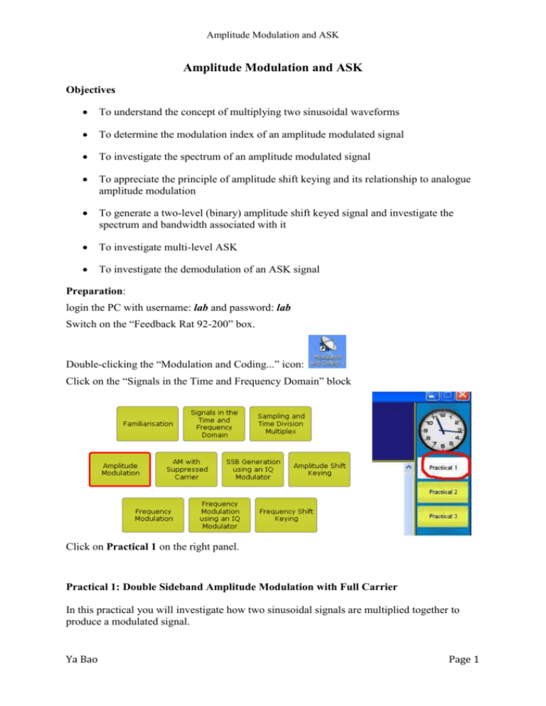
Amplitude Modulation and ASK Amplitude Modulation and ASK Objectives To understand the concept of multiplying two sinusoidal waveforms To determine the modulation index of an amplitude modulated signal To investigate the spectrum of an amplitude modulated signal To appreciate the principle of amplitude shift keying and its relationship to analogue amplitude modulation To generate a two-level (binary) amplitude shift keyed signal and investigate the spectrum and bandwidth associated with it To investigate multi-level ASK To investigate the demodulation of an ASK signal Preparation: login the PC with username: lab and password: lab Switch on the “Feedback Rat 92-200” box. Double-clicking the “Modulation and Coding...” icon: Click on the “Signals in the Time and Frequency Domain” block Click on Practical 1 on the right panel. Practical 1: Double Sideband Amplitude Modulation with Full Carrier In this practical you will investigate how two sinusoidal signals are multiplied together to produce a modulated signal. Ya Bao Page 1 Amplitude Modulation and ASK Procedure 1. Click Make Connections, follow it to complete all connections on the board. 2. Open the voltmeter and use it to set the dc Source voltage to give a Carrier offset of approximately +0.25 volts. 3. Set the modulating signal amplitude (I Mod) by adjusting the Signal Level Control to half scale. 4. In the IQ Modulator block, set all of the controls to half scale. 5. Open the oscilloscope and note the waveform on the upper trace (the modulated waveform). Compare it to that on the lower trace (the modulating waveform). 6. Connect the voltmeter probe (green) to the modulating signal (monitor point 3) and set the voltmeter functions to ac p-p. Use the Signal Level Control to set the amplitude of the modulating signal to 0.25 volts peak to peak. 7. Enlarge the osciloscope window. Use the oscilloscope cursors to measure the values A1 and A2 shown below. Use the formula to calculate modulation index m. m A1 A2 A1 A2 8. Try other values of modulation signal amplitude and measure A1 and A2 and thus calculate m. Compare the values with the ratios of the modulation signal peak value to the dc offset. Use an Excel spreadsheet to tabulate your results Note that the voltmeter reads peak to peak values when choose ac. 9. Open the Spectrum Analyser and observe the spectrum (in large window) of the modulated signal (monitor point 4). Adjust the modulation amplitude using the Signal Level Control and observe the spectrum. Use the cursors to measure the relative levels of the two sidebands to the carrier at m=1, 0.5 and 0. 10. Move the Spectrum Analyser probe (orange) to the modulation source (monitor point 3). Measure modulating frequency using the cursor. 11. Return to the modulated output (monitor point 4) and measure the frequencies of the two sidebands. Calculate the frequency difference between the carrier and the upper sideband, and the carrier and the lower sideband. Ya Bao Page 2 Amplitude Modulation and ASK 12. Now measure the modulating frequency on point 3 by Frequency counter. Compare the values. 13. Set the modulation index to 1 using the oscilloscope display. Practical 2, 3 and 4 are located in Amplitude Shift Keying block. Click on the “Amplitude Shift Keying” block. Click on Practical 1 on the right panel. Practical 2: Generating Amplitude Shift Keying Procedures 1. Click Make Connections, follow it to complete all connections (excluding “add later” links) on the board. 2. Open the oscilloscope and the spectrum analyser. 3. Set the modulation Signal Level Control and the IQ Modulator block controls to approximately half scale. 4. Set the Function Generator to Fast and the output to a square wave. Adjust the Frequency until two cycles of waveforms shown on the osilloscope. 5. Open the voltmeter and set the Carrier offset voltage to approximately +0.25 volts using the dc Source control. Close the voltmeter. 6. Enlarge the oscilloscope window. Use the oscilloscope cursor to measure and adjust the Frequency on the function generator so that the ‘bit’ period is about 20 μS. Adjust the modulation Signal Level Control so that, for a bit zero, the amplitude of the carrier is almost zero. The oscilloscope should now show amplitude shift keying. Record the sidebands on the spectrum analyser. 7. Change the Frequency of the function generator and note the effect. Comment on your observations. 8. Open the Phasescope. 9. Move the reference probe (yellow) for the phase scope to the carrier (monitor point 1) Ya Bao Page 3 Amplitude Modulation and ASK and note the constellation. Change Signal Level Control to adjuste the amplitude of the carrier, explain your obvservations. 10. Return the probe to the data signal (monitor point 2). 11. Refer to the Make Connections diagram and remove connection 1 and add connections 10 and 11. This places a pre-modulation filter in circuit. Adjust the function generator back to 20 μS bit period. Note the waveform and bandwidth. Compare the observations with that gain in step 6. 12. Increase the frequency of the function generator you will see that if the bit rate is too near the filter cut-off then significant inter-symbol interference takes place. Practical 3: Generating Multi Level Amplitude Shift Keying In this practical you will investigate 4-level ASK. Procedures 1. Click Make Connections, follow it to complete all connections on the board. 2. Open the voltmeter and set the Carrier offset voltage to +0.25 volts using the dc Source control. 3. Set the modulation Signal Level Control and the IQ Modulator block controls to approximately half scale. 4. Open the oscilloscope and look at the signals. You should see that the modulating data (blue trace) contains a finite number of different levels within the waveform. Decrease the oscilloscope timebase, if necessary, to see this more clearly. The modulated signal (yellow trace) contains the same number of carrier amplitudes. This is 16-level ASK. 5. Think about the relationship between symbol rate and bit rate. Work out how much higher the bit rate is for the same symbol rate as binary ASK. 6. Change to 4-level and 8-level and observe the effects. Practical 4: Demodulating Amplitude Shift Keying Procedure: 1. Click Make Connections, follow it to complete all connections on the board. 2. Ensure that the balance controls associated with the IQ Modulator and IQ Demodulator blocks are set to their mid positions. 3. Open the oscilloscope and the spectrum analyser. 4. Open the voltmeter and set the dc Carrier offset voltage to +0.25 volts using the lefthand dc Source control. 5. Set the Function Generator to Fast and select a square wave output. 6. Set the modulation Signal Level Control to about half scale. Ya Bao Page 4 Amplitude Modulation and ASK 7. Adjust the Function Generator Frequency so you can see at least one cycle of data on the screen. Use the Signal Level Control to adjust the modulation level to 100%. This would correspond with the greatest probability of receiving data with no errors. Note we are not using a pre-modulation filter, so the spectrum is very wide. 8. Move the oscilloscope Channel 1 probe (blue) to the envelope detector output (point 5). Record your observations. (Note that the output signal follows the modulation, although the edges are not so fast). 9. Adjust the modulation level using the Signal Level Control and compare the output waveforms. Note that the output from the envelope detector is at maximum when the modulation is 100%. Confirm that increasing the signal level further does not affect the amplitude of the output from the envelope detector. References: Feedback software help files. Ya Bao Page 5

