1 - Cabrillo College
advertisement

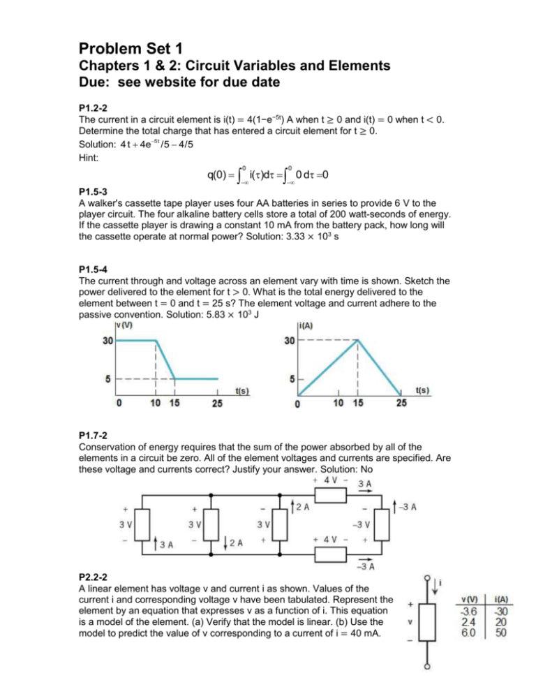
Problem Set 1 Chapters 1 & 2: Circuit Variables and Elements Due: see website for due date P1.2-2 The current in a circuit element is i(t) = 4(1−e−5t) A when t ≥ 0 and i(t) = 0 when t < 0. Determine the total charge that has entered a circuit element for t ≥ 0. Solution: 4 t 4e5t /5 4/5 Hint: 0 0 q(0) i()d 0 d 0 P1.5-3 A walker's cassette tape player uses four AA batteries in series to provide 6 V to the player circuit. The four alkaline battery cells store a total of 200 watt-seconds of energy. If the cassette player is drawing a constant 10 mA from the battery pack, how long will the cassette operate at normal power? Solution: 3.33 × 10³ s P1.5-4 The current through and voltage across an element vary with time is shown. Sketch the power delivered to the element for t > 0. What is the total energy delivered to the element between t = 0 and t = 25 s? The element voltage and current adhere to the passive convention. Solution: 5.83 × 10³ J P1.7-2 Conservation of energy requires that the sum of the power absorbed by all of the elements in a circuit be zero. All of the element voltages and currents are specified. Are these voltage and currents correct? Justify your answer. Solution: No P2.2-2 A linear element has voltage v and current i as shown. Values of the current i and corresponding voltage v have been tabulated. Represent the element by an equation that expresses v as a function of i. This equation is a model of the element. (a) Verify that the model is linear. (b) Use the model to predict the value of v corresponding to a current of i = 40 mA. 1 (c) Use the model to predict the value of i corresponding to a voltage of v = 4 V. Solution: 4.8 mV, 33.3 A P2.4-3 A voltage source and a resistor are connected in parallel in the circuit. Elements connected in parallel have the same voltage, so v = vs in this circuit. Calculate the current i in the resistor and the power absorbed by the resistor. Solution: 2 A, 20 W P2.4-6 A current source and two resistors are connected in series in the circuit. Elements connected in series have the same current. Calculate the voltage across each resistor and the power absorbed by each resistor. Solution: −8 V, 16 V, 16 W, 32 W P2.5-2 A current source and a voltage source are connected in series with a resistor. (a) Calculate the voltage and power absorbed by the resistor. (b) Change the voltage source voltage to 5V and recalculate the voltage and power absorbed by the resistor. (c) Explain the results. Solution: 10V, 20W; same as (a) P2.7-4 The voltmeters in the circuit indicate that va = 2 V and vb = 8 V. Determine the value of b, the gain of the VCVS. Solution: 4 V/V 2 P2.10-2 The circuit is used to measure the current in the resistor. Once this current is known, the resistance can be calculated as R = vS/i. The circuit is constructed using a 25-Ω, ½-W resistor. After a puff of smoke and an unpleasant smell, the ammeter indicates that i = 0 A. The resistor must be bad. You have more 25-Ω, ½-W resistors. Should you try another resistor? Justify your answer. Partial Solution: 5.76 W Hint: ½-W resistors are able to safely dissipate one ½-W of power. These resistors may fail if required to dissipate more than ½-W of power. DP2-2 Specify the resistance R so that both of the following conditions are satisfied: 1. v > 40 V. 2. The power absorbed by the resistor is less than 15 W. Hint: There is no guarantee that specifications can always be satisfied. Solution: No 3


