t6_bcurrents
advertisement
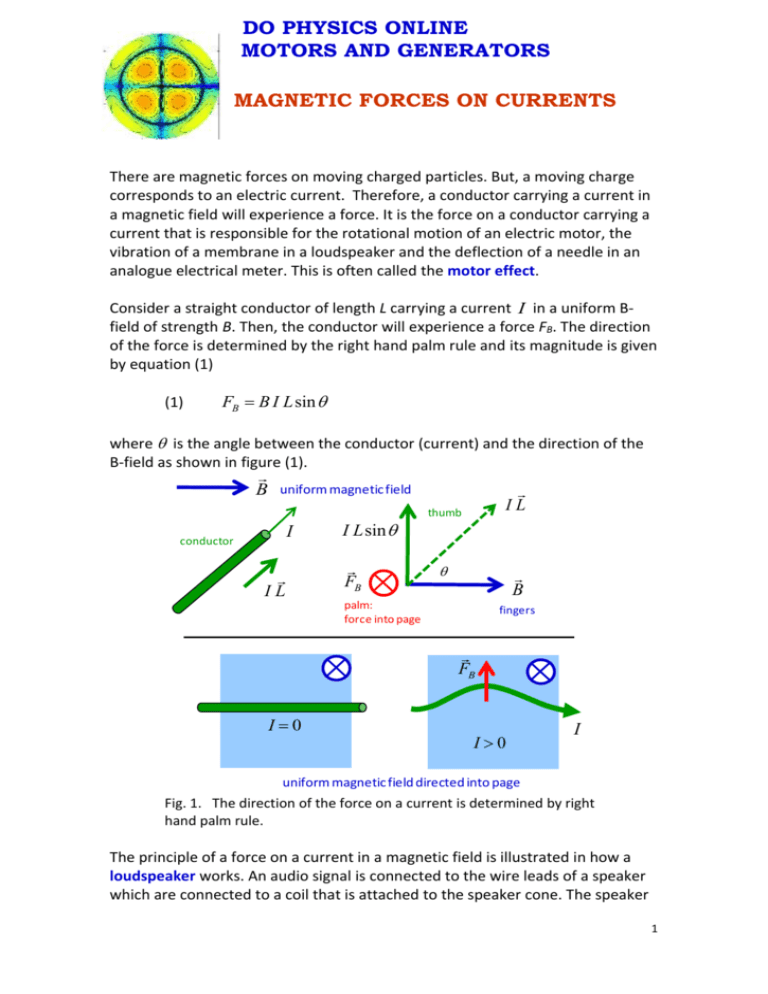
DO PHYSICS ONLINE MOTORS AND GENERATORS MAGNETIC FORCES ON CURRENTS There are magnetic forces on moving charged particles. But, a moving charge corresponds to an electric current. Therefore, a conductor carrying a current in a magnetic field will experience a force. It is the force on a conductor carrying a current that is responsible for the rotational motion of an electric motor, the vibration of a membrane in a loudspeaker and the deflection of a needle in an analogue electrical meter. This is often called the motor effect. Consider a straight conductor of length L carrying a current I in a uniform Bfield of strength B. Then, the conductor will experience a force FB. The direction of the force is determined by the right hand palm rule and its magnitude is given by equation (1) (1) FB B I L sin where is the angle between the conductor (current) and the direction of the B-field as shown in figure (1). B uniform magnetic field I conductor IL I L sin FB IL thumb B palm: force into page fingers FB I0 I0 I uniform magnetic field directed into page Fig. 1. The direction of the force on a current is determined by right hand palm rule. The principle of a force on a current in a magnetic field is illustrated in how a loudspeaker works. An audio signal is connected to the wire leads of a speaker which are connected to a coil that is attached to the speaker cone. The speaker 1 cone is mounted so that it is free to vibrate back and forth. A permanent magnet is aligned with the coil in such a way that when a current passes through the coil, the force on the conductor can move the speaker cone in or out. When an alternating current of the audio signal is connected to the coil, the force on the conductor alternates at the frequency of the audio signal. The speaker cone vibrates producing a series of compressions and rarefactions of the adjacent air, thus producing the sound wave with frequencies and intensities to give a reproduction of the electrical signal and the original sound signal. The main features of a loudspeaker are shown in figure (2). coil winding attached to speaker cone B-field current through coils N I S force on cone N speaker cone permanent magnet rigid frame attached to magnet and speaker cone Fig. 2. Loudspeaker. When a AC current passes through the coil, an alternating force moves the speaker back and forth to produce the sound wave. An any instant, the direction of the force on the speaker can be determined from the right hand palm rule. v q I right hand palm rule F 2 Magnetic force between two parallel current carrying conductors A conductor carrying a current has a magnetic field surrounding it. A conductor carrying a current in a magnetic field experience a force. Hence, two current parallel carrying conductors will exert a force on each other. Figure 3 shows the force F21 acting on conducting 2 (current I2) due to the magnetic field surrounding conductor 1 (current 1). The direction of the force is given by the right hand rule. When the currents are in the same direction, the conductors are attracted to each other. currents I1 and I2 are into page F21 1 force on conductor 2 due to conductor 1 2 B1 d think of two railway tracks merging in the distance – currents in the same direction attract I1 I2 F d Fig. 2. Two parallel conductors carrying currents in the same direction are attracted to each other. When the currents are in opposite directions, the conductors repel each other as shown in figure (3). 3 current I1 out of page and I2 are into page B2 force on conductor 1 due to conductor 2 1 2 F21 I1 d F F d I2 Fig. 3. Two parallel conductors carrying currents in opposite directions are repelled to each other. At the location of conductor 2, the B-field from conductor 1 is B1 o I1 2 d The magnitude of the on force conductor 2 in this B-field is F2 B 1I 2 L I I F2 o 1 2 L 2 d Hence, we can conclude, that the force per unit length between two parallel conductors is (1) F o I1 I 2 I I k 1 2 L 2 d d k o 2 o 4 107 T.m.A-1 The right hand palm rule can be used to determine the direction of the force between the conductors. Example There are two parallel horizontal conductors. The first conductor has a current of 100 A. The second conductor lies 350 mm directly below the first conductor. The second conductor has a mass of 0.150 g.m-1. What is the minimum current through the second conductor so that it does not fall due to gravity? What are the directions of the currents? 4 Solution How to a approach the problem Draw a diagram of the situation: labelled with known and unknown quantities Type of problem: force between parallel conductors: F o I1 I 2 L 2 d FG mg Magnetic force: Weight : For the conductor 2 to be balanced, the gravitational force must equal the magnetic force and the conductors must attract each other. Therefore, the currents I1 and I2 must be in the same direction. I1 = 100 A FB d = 0.350 m currents in same direction attract I2 = ? A FG = mg = (m/L) g L g = 9.81 m.s-2 m/L = 0.150 g.m-1 = 1.50×10⁻⁴ kg.m-1 o = 4×10⁻⁷ T.m.A-1 o / 2 = 2×10⁻⁷ T.m.A-1 FG m g FG / L m / L g I I FB / L o 1 2 2 d Gravitational force: Magnetic force: Forces balance to support 2nd conductor m / L g o I1 I 2 2 d We can rearrange to find the current I2 m / L g d I2 o / 2 I1 (1.5 104 ) 9.81 0.35 2.0 10 100 7 P6021 P6091 P6276 P6382 P6547 P6576 P6622 P6788 P6461 A 25.8 A P6464 P6481 P6859 5

